IPexpert’s IPv6 eBook
IPexpert’s IPv6 eBook and Advanced
IPv6 Lab Scenario
•
•
•
•
•
•
•
•
•
•
•
•
•
•
•
•
•
•
•
•
•
•
•
IPv6 Addressing
General Addressing format
Addressing convention
IPv6 address types
Global Address
Link Local vs. Site Local
IPv4 in IPv6 addresses
Anycast
Multicast Addresses
IPv6 Packet Header Format
ICMP
DNS
DHCP
Ethernet
Frame Relay
RIP
OSPF
BGP
Mobile IPv6
DSCP
Tunneling
IP6to4
Security
Copyright IPexpert, Inc. (http://www.IPexpert.com) 2005. All Rights Reserved.
2
IPexpert’s IPv6 eBook
Introduction
IPv6 was proposed when it became clear that the 32 bit addressing scheme of IP version 4 (IPv4)
was inadequate to meet the demands of Internet growth. IPv6 has a larger address space. The
architecture of IPv6 was designed to allow existing IPv4 users to transition easily to IPv6, while
providing services such as end-to-end security, Quality of Service (QoS), and globally unique
addresses. The larger IPv6 address space allows networks to scale and provide global
reachability. The simplified IPv6 packet header format handles packets more efficiently. IPv6
supports widely deployed routing protocols such as RIP, IS-IS, OSPF, and multiprotocol BGP.
IPv6 Addressing
IPv6 addresses are 128-bit identifiers for interfaces and sets of interfaces. These are represented
as a series of 16-bit hexadecimal fields and each 16-bit block is converted to a 4-digit
hexadecimal number separated by colons (:) in the format: x:x:x:x:x:x:x:x. The resulting
representation is called colon-hexadecimal. The IPv6 addressing architecture is described in RFC
3513.
There are three types of addresses:
• Unicast: An identifier for a single interface. A packet sent to a unicast address is
delivered to the interface identified by that address.
• Anycast: An identifier for a set of interfaces (typically belonging to different nodes). A
packet sent to an anycast address is delivered to one of the interfaces identified by that
address (the "nearest" one, according to the routing protocols’ measure of distance).
Anycast addresses are taken from the unicast address spaces (of any scope) and are not
syntactically distinguishable from unicast addresses.
• Multicast: An identifier for a set of interfaces (typically belonging to different nodes). A
packet sent to a multicast address is delivered to all interfaces identified by that address.
There are no broadcast addresses in IPv6, their function being superseded by multicast
addresses.
IPv6 addresses of all types are assigned to interfaces, not nodes. An IPv6 unicast address refers
to a single interface. Since each interface belongs to a single node, any of that node’s interface
unicast addresses may be used as an identifier for the node.
General Addressing format
The general format for IPv6 global unicast addresses is as follows:
n bits
m bits
128-n-m bits
Global routing prefix
Subnet ID
Interface ID
•
•
global routing prefix - value assigned to a site
subnet ID - an identifier of a link within the site
It is also required that all unicast addresses, except those that start with binary value 000, have
Interface IDs that are 64 bits long and must be constructed in Modified EUI-64 format. The format
of global unicast address in this case is:
Copyright IPexpert, Inc. (http://www.IPexpert.com) 2005. All Rights Reserved.
3
IPexpert’s IPv6 eBook
n bits
64-n bits
64 bits
Global routing prefix
Subnet ID
Interface ID
Addressing convention
There are some conventions for representing IPv6 addresses as text strings:
• It is common for IPv6 addresses to contain successive hexadecimal fields of zeros. To
make IPv6 addresses less cumbersome, two colons (::) may be used to compress
successive hexadecimal fields of zeros at the beginning, middle, or end of an IPv6
address (the colons represent successive hexadecimal fields of zeros).
• The preferred form is x:x:x:x:x:x:x:x, where the ’x’s are the hexadecimal values of the
eight 16-bit pieces of the address. Note that it is not necessary to write the leading zeros
in an individual field, but there must be at least one numeral in every field.
• Due to some methods of allocating certain styles of IPv6 addresses, it will be common for
addresses to contain long strings of zero bits. In order to make writing addresses
containing zero bits easier, a special syntax is available to compress the zeros. The use
of "::" indicates one or more groups of 16 bits of zeros. The "::" can only appear once in
an address. The "::" can also be used to compress leading or trailing zeros in an address.
For example, the following addresses:
•
Type
Full Address
Simplified Address
Unicast address
1234:0:0:0:8:888:200C:4444 1234::8:888:200C:4444
Multicast
FF01:0:0:0:0:0:0:123
FF01::123
0:0:0:0:0:0:0:1
::1
0:0:0:0:0:0:0:0
::
address
Loopback
address
Unspecified
address
The loopback address may be used by a node to send an IPv6 packet to itself.
The loopback address in IPv6 functions the same as the loopback address in
IPv4 (127.0.0.1).
o The unspecified address indicates the absence of an IPv6 address. For example,
a newly initialized node on an IPv6 network may use the unspecified address as
the source address in its packets until it receives its IPv6 address.
An alternative form that is sometimes more convenient when dealing with a mixed
environment of IPv4 and IPv6 nodes is x:x:x:x:x:x:d.d.d.d, where the ’x’s are the
hexadecimal values of the six high-order 16-bit pieces of the address, and the ’d’s are the
decimal values of the four low-order 8-bit pieces of the address (standard IPv4
representation). Examples:
0:0:0:0:0:0:13.1.68.3
0:0:0:0:0:FFFF:129.144.52.38
o
•
Copyright IPexpert, Inc. (http://www.IPexpert.com) 2005. All Rights Reserved.
4
IPexpert’s IPv6 eBook
The text representation of IPv6 address prefixes is similar to the way IPv4 address prefixes are
written in Classless Inter-Domain Routing (CIDR) notation. An IPv6 address prefix is represented
by the notation: ipv6-address/prefix-length
IPv6 address types
The type of an IPv6 address is identified by the high-order bits of the address, as follows:
Address Type
Binary Prefix
Ipv6 notation
Unspecified
000…000 (128 bits)
::/128
Loopback
000…001 (128 bits)
::1/128
Multicast
11111111
FF00::/8
Link-local unicast
1111111010
FE80::/10
Site-local unicast
1111111011
FEC0::/10
Global unicast
Everything else
Interface identifiers in IPv6 unicast addresses are used to identify interfaces on a link. They are
required to be unique within a subnet prefix. It is recommended that the same interface identifier
not be assigned to different nodes on a link. They may also be unique over a broader scope.
For all unicast addresses, except those that start with binary value 000, Interface IDs are required
to be 64 bits long and to be constructed in Modified EUI-64 format. In addition:
• The address 0:0:0:0:0:0:0:0 is called the unspecified address. It must never be assigned
to any node. It indicates the absence of an address.
• The unicast address 0:0:0:0:0:0:0:1 is called the loopback address. It may be used by a
node to send an IPv6 packet to itself.
Global Address
Aggregate-able global addresses are used on links that are aggregated upward through
organizations,
•
•
•
•
3 bits
45 bits
16 bits
64 bits
001
Routing Prefix
SLA
Interface ID
001 - identifies the address as being an aggregate-able global address.
Routing Prefix - included two other hierarchically structured fields named Top-Level
Aggregator (TLA) and Next-Level Aggregator (NLA).
SLA – subnet ID, used by individual organizations to create their own local addressing
hierarchy and to identify subnets.
Interface ID - must be unique to the link.
Copyright IPexpert, Inc. (http://www.IPexpert.com) 2005. All Rights Reserved.
5
IPexpert’s IPv6 eBook
Link Local vs. Site Local
There are two types of local-use unicast addresses defined:
• Link-Local - for use on a single link. Routers must not forward any packets with link-local
source or destination addresses to other links. Link-Local addresses are designed to be
used for addressing on a single link for purposes such as automatic address
configuration, neighbor discovery, or when no routers are present.
•
10 bits
54 bits
64 bits
1111111010
000…000
Interface ID
Site-Local - for addressing inside a site without the need for a global prefix. Routers
must not forward any packets with site-local source or destination addresses outside of
the site.
10 bits
54 bits
64 bits
1111111011
Subnet ID
Interface ID
IPv4 in IPv6 addresses
The IPv6 transition mechanisms include a technique for hosts and routers to tunnel dynamically
IPv6 packets over IPv4 routing infrastructure. IPv6 nodes that use this technique are assigned
special IPv6 unicast addresses that carry a global IPv4 address in the low-order 32 bits. This type
of address is termed an "IPv4-compatible IPv6 address" and has the format:
80 bits
16 bits
32 bits
000…000
0000
IPv4 address
A second type of IPv6 address that holds an embedded IPv4 address is also defined. This
address type is used to represent the addresses of IPv4 nodes as IPv6 addresses. This type of
address is termed an "IPv4-mapped IPv6 address" and has the format:
80 bits
16 bits
32 bits
000…000
FFFF
IPv4 address
Anycast
An IPv6 anycast address is an address that is assigned to more than one interface (typically
belonging to different nodes), with the property that a packet sent to an anycast address is routed
to the "nearest" interface having that address, according to the routing protocols’ calculation.
Anycast addresses are allocated from the unicast address space, using any of the defined
unicast address formats. Thus, anycast addresses are syntactically indistinguishable from unicast
addresses. When a unicast address is assigned to more than one interface, thus turning it into an
Copyright IPexpert, Inc. (http://www.IPexpert.com) 2005. All Rights Reserved.
6
IPexpert’s IPv6 eBook
anycast address, the nodes to which the address is assigned must be explicitly configured to
know that it is an anycast address. Its format is as follows:
•
n bits
128-n bits
Subnet prefix
000…000
subnet prefix - identifies a specific link
Here is the limitation for anycast:
• An anycast address must not be used as the source address of an IPv6 packet.
• An anycast address must not be assigned to an IPv6 host, that is, it may be assigned to
an IPv6 router only.
Multicast Addresses
An IPv6 multicast address is an identifier for a group of interfaces (typically on different nodes).
An interface may belong to any number of multicast groups. Multicast addresses have the
following format:
•
•
•
•
8 bits
4 bits
4 bits
112 bits
11111111
Flgs = 000T
Scope
Group ID
11111111 - identifies the address as being a multicast address.
flgs = 000T
T = 0 indicates a permanently-assigned ("well-known") multicast address.
T = 1 indicates a non-permanently-assigned ("transient") multicast address.
scope - limit the scope of the multicast group. The values are:
1
interface-local scope
2
link-local scope
4
admin-local scope
5
site-local scope
8
organization-local scope
E
global scope
0, 3, F
reserved
6, 7, 9 – D
(unassigned)
group ID - identifies the multicast group, either permanent or transient, within the given
scope.
Copyright IPexpert, Inc. (http://www.IPexpert.com) 2005. All Rights Reserved.
7
IPexpert’s IPv6 eBook
IPv6 Packet Header Format
0
1
2
3
Version
4
5
6
7
8
9
0
1
2
3
4
5
6
7
8
9
Traffic Class
0
1
2
3
4
5
6
7
8
Flow Label
Payload Length
Next Header
Hop Limit
Source Address
Destination Address
Next Header
Extension Header Information
Data
•
•
•
•
•
•
•
•
9
Version – IPv6.
Traffic Class - Similar to the Type of Service field in the IPv4 packet header.
Flow Label - Tags packets with a specific flow that differentiates the packets at the
network layer.
Payload Length - Indicates the total length of the data portion of the packet.
Next Header - Determines the type of information following the basic IPv6 header.
Hop Limit - Specifies the maximum number of routers that an IPv6 packet can pass
through before the packet is considered invalid.
Source Address - 128-bit source address for IPv6.
Destination Address - 128-bit destination address for IPv6.
ICMP
ICMPv6 is used by IPv6 nodes to report errors encountered in processing packets and to perform
other internet-layer functions. ICMPv6 is an integral part of IPv6 and must be fully implemented
by every IPv6 node.
ICMPv6 messages are grouped into two classes: error messages and informational messages.
Error messages are identified as such by having a zero in the high-order bit of their message
Type field values. Thus, error messages have message Types from 0 to 127; informational
messages have message Types from 128 to 255.
• ICMPv6 error messages: Destination Unreachable, Packet Too Big, Time Exceeded,
and Parameter Problem.
• ICMPv6 informational messages: Echo Request and Echo Reply.
Copyright IPexpert, Inc. (http://www.IPexpert.com) 2005. All Rights Reserved.
8
0
1
IPexpert’s IPv6 eBook
Every ICMPv6 message is preceded by an IPv6 header and zero or more IPv6 extension
headers. The ICMPv6 header is identified by a Next Header value of 58 in the immediately
preceding header. The ICMPv6 messages have the following general format:
0
1
2
3
4
5
Type (1)
6
7
8
9
0
1
2
3
4
5
6
7
8
Code (1)
9
0
1
2
3
4
5
6
7
8
Checksum (2)
Message Body
•
•
•
Type - The type of the message.
Code - Create an additional level of message granularity.
Checksum - Detect data corruption in the ICMPv6 message and parts of the IPv6
header.
DNS
IPv6 introduces new DNS record types that are supported in the DNS name-to-address and
address-to-name lookup processes. The new DNS record types support IPv6 addresses. The
DNS Recursive Name Server option provides a list of one or more IPv6 addresses of DNS
recursive name servers to which a client’s DNS resolver MAY send DNS queries. The DNS
servers are listed in the order of preference for use by the client resolver. The Domain Search List
option specifies the domain search list the client is to use when resolving hostnames with DNS.
This option does not apply to other name resolution mechanisms.
The DNS Recursive Name Server option may be used by an intruder DHCP server to cause
DHCP clients to send DNS queries to an intruder DNS recursive name server. The results of
these misdirected DNS queries may be used to spoof DNS names. To avoid attacks through the
DNS Recursive Name Server option, the DHCP client SHOULD require DHCP authentication
before installing a list of DNS recursive name servers obtained through authenticated DHCP.
Support for IPv6.arpa reverse lookups is not in the current release of the Cisco IOS software.
DHCP
A delegating router is provided IPv6 prefixes to be delegated to requesting routers. The
delegating router chooses prefix(es) for delegation, and responds with prefix(es) to the requesting
router. The requesting router is then responsible for the delegated prefix(es). For example, the
requesting router might assign a subnet from a delegated prefix to one of its interfaces, and begin
sending router advertisements for the prefix on that link.
Each prefix has an associated valid and preferred lifetime, which constitutes an agreement about
the length of time over which the requesting router is allowed to use the prefix. A requesting
router can request an extension of the lifetimes on a delegated prefix and is required to terminate
the use of a delegated prefix if the valid lifetime of the prefix expires. This prefix delegation
mechanism would be appropriate for use by an ISP to delegate a prefix to a subscriber, where
the delegated prefix would possibly be subnetted and assigned to the links within the subscriber’s
network.
Copyright IPexpert, Inc. (http://www.IPexpert.com) 2005. All Rights Reserved.
9
9
0
1
IPexpert’s IPv6 eBook
Prefix delegation with DHCP is independent of address assignment with DHCP. A requesting
router can use DHCP for just prefix delegation or for prefix delegation along with address
assignment and other configuration information.
The DHCP for IPv6 implementation in the Cisco IOS Release 12.3(4)T supports only stateless
address assignment, in this case, configuration parameters that do not require a server to
maintain any dynamic state for individual clients, such as DNS server addresses and domain
search list options. The DHCP for IPv6 client, server, and relay functions are mutually exclusive
on an interface. When one of these functions is already enabled and a user tries to configure a
different function on the same interface, one of the following messages is displayed: “Interface is
in DHCP client mode,” “Interface is in DHCP server mode,” or “Interface is in DHCP relay mode.”
Ethernet
The default MTU size for IPv6 packets on an Ethernet is 1500 octets. IPv6 packets are
transmitted in standard Ethernet frames. The Ethernet header contains the Destination and
Source Ethernet addresses and the Ethernet type code, which must contain the value 86DD
hexadecimal. The data field contains the IPv6 header followed immediately by the payload, and
possibly padding octets to meet the minimum frame size for the Ethernet link.
0
1
2
3
4
5
6
7
8
9
0
1
2
3
4
5
Destination Ethernet Address (6)
Source Ethernet Address (6)
IPv6 Header and payload
The Interface Identifier for an Ethernet interface is based on the EUI-64 identifier derived from the
interface’s built-in 48-bit IEEE 802 address. The OUI of the Ethernet address (the first three
octets) becomes the company_id of the EUI-64 (the first three octets). The fourth and fifth octets
of the EUI are set to the fixed value FFFE hexadecimal. The last three octets of the Ethernet
address become the last three octets of the EUI-64.
The Interface Identifier is then formed from the EUI-64 by complementing the "Universal/Local"
(U/L) bit, which is the next-to- lowest order bit of the first octet of the EUI-64. Complementing this
bit will generally change a 0 value to a 1, since an interface’s built-in address is expected to be
from a universally administered address space and hence have a globally unique value. A
universally administered IEEE 802 address or an EUI-64 is signified by a 0 in the U/L bit position,
while a globally unique IPv6 Interface Identifier is signified by a 1 in the corresponding position.
For example, the Interface Identifier for an Ethernet interface whose built-in address is, in
hexadecimal, 34-56-78-9A-BC-DE would be 36-56-78-FF-FE-9A-BC-DE.
Copyright IPexpert, Inc. (http://www.IPexpert.com) 2005. All Rights Reserved.
10
IPexpert’s IPv6 eBook
The IPv6 link-local address for an Ethernet interface is formed by appending the Interface
Identifier to the prefix FE80::/64.
10 bits
54 bits
64 bits
1111111010
All zero
Interface ID
Frame Relay
In general, Frame Relay devices are configured to have a maximum frame size of at least 1600
octets. Therefore, the default IPv6 MTU size for a Frame Relay interface is considered to be
1592. A smaller than default frame size can be configured, but not smaller than the minimum IPv6
MTU. Although a Frame Relay circuit allows the definition of distinct maximum frame sizes for
input and output, for simplification purposes, this specification assumes symmetry, i.e., the same
MTU for both input and output.
The encapsulation of data or control messages exchanged by various protocols that use SNAP
encapsulation (with their own PIDs) is not affected. The encoding of the IPv6 protocol identifier in
such messages MUST be done according to the specifications of those protocols.
An interface identifier for an IPv6 Frame Relay interface must be unique on a Frame Relay link,
and must be unique on each of the virtual links represented by the VCs terminated on the
interface. The interface identifier for the Frame Relay interface is locally generated by the IPv6
module.
Given that IPv6 supports multiple address types, and depending on which applications or
protocols are configured on a point-to-multipoint interface, you may need to configure multiple
explicit mappings between the IPv6 addresses of the interface and the PVC used to reach the
addresses. For example, explicitly mapping both the link-local and global IPv6 address of a pointto-multipoint interface to the PVC that the interface terminates ensures that the Interior Gateway
Protocol configured on the interface forwards traffic to and from the PVC correctly.
RIP
RIP has been used for routing computations in computer networks since the early days of the
ARPANET. RIPng (Routing Information Protocol next generation) uses a class of algorithms
known as Distance Vector algorithms. It is intended to allow routers to exchange information for
computing routes through an IPv6-based network. RIPng is a distance vector routing protocol and
should be implemented only in routers. The RIPng metric of a network is an integer between 1
and 15, inclusive. In addition to the metric, each network will have an IPv6 destination address
prefix and prefix length associated with it. These are to be set by the system administrator in a
manner not specified in this protocol.
RIPng is a UDP-based protocol. Each router that uses RIPng has a routing process that sends
and receives datagrams on UDP port number 521, the RIPng port. All communications intended
for another router’s RIPng process are sent to the RIPng port. All routing update messages are
sent from the RIPng port. The RIPng packet format is:
0
1
2
3
4
5
6
Command (1)
7
8
9
0
1
2
3
Version (1)
4
5
6
7
8
9
0
1
2
3
4
5
6
7
8
Zeros (2)
Copyright IPexpert, Inc. (http://www.IPexpert.com) 2005. All Rights Reserved.
11
9
0
1
IPexpert’s IPv6 eBook
Routing Table Entry #1 (20)
…
Routing Table Entry #N (20)
In addition, each Route Table Entry (RTE) has the following format:
0
1
2
3
4
5
6
7
8
9
0
1
2
3
4
5
6
7
8
9
0
1
2
3
4
5
6
7
8
9
IPv6 prefix (16)
Route tag (2)
•
•
•
•
•
•
Prefix len (1)
Metrix (1)
Command field - to specify the purpose of this message, either request or response.
RTE - contains destination prefix, the number of significant bits in the prefix, and the cost
to reach that destination (metric).
Destination prefix - the usual 128-bit, IPv6 address prefix stored as 16 octets in network
byte order.
Route tag field - an attribute assigned to a route that must be preserved and readvertised with a route.
Prefix length field - the length in bits of the significant part of the prefix (a value between
0 and 128 inclusive) starting from the left of the prefix.
Metric field - contains a value between 1 and 15 inclusive, or the value 16 (infinity),
which indicates that the destination is not reachable.
The distinction between network, subnet, and host routes does not need to be made for RIPng
because an IPv6 address prefix is unambiguous. Every 30 seconds, the RIPng process is
awakened to send an unsolicited Response message, containing the complete routing table to
every neighboring router (subject to the split-horizon rule).
OSPF
Most of the algorithms from OSPF (Open Shortest Path First) for IPv4 have been preserved in
OSPF for IPv6. However, some changes have been necessary. Here are some of the key points:
• In OSPF for IPv6, neighboring routers on a given link are always identified by their OSPF
Router ID.
• Flooding scope for LSAs has been generalized and is now explicitly coded in the LSAs
LS type field. There are now three separate flooding scopes for LSAs: Link-local scope,
Area scope, and AS scope.
• IPv6 link-local addresses are for use on a single link, for purposes of neighbor discovery,
auto-configuration, etc. IPv6 routers do not forward IPv6 datagrams having link-local
source addresses.
• In OSPF for IPv6, authentication has been removed from OSPF itself. All authenticationrelated fields have been removed from the OSPF area and interface structures. When
Copyright IPexpert, Inc. (http://www.IPexpert.com) 2005. All Rights Reserved.
12
0
1
IPexpert’s IPv6 eBook
running over IPv6, OSPF relies on the IP Authentication Header and the IP
Encapsulating Security Payload to ensure integrity and authentication/confidentiality of
routing exchanges.
All addressing semantics have been removed from the OSPF packet headers, making it
essentially "network-protocol-independent."
Handling of unknown LSA types has been made more flexible so that, based on LS type,
unknown LSA types are either treated as having link-local flooding scope, or are stored
and flooded as if they were understood.
OSPF now supports the ability to run multiple OSPF protocol instances on a single link.
In OSPF for IPv6, addressing semantics have been removed from the OSPF protocol
packets and the main LSA types, leaving a network-protocol-independent core.
IPv6 uses the term "link" to indicate "a communication facility or medium over which
nodes can communicate at the link layer.” OSPF for IPv6 runs per-link instead of the IPv4
behavior of per-IP-subnet.
•
•
•
•
•
There are five distinct OSPF packet types. All OSPF packet types begin with a standard 16-byte
header. The OSPF header contains all the information necessary to determine whether the
packet should be accepted for further processing.
0
1
2
3
4
5
6
Version # (1)
7
8
9
0
1
2
3
4
5
6
7
8
Type (1)
9
0
1
2
3
4
5
6
7
8
9
0
Packet Length (2)
Router ID (4)
Area ID (4)
Checksum (2)
•
•
•
•
•
•
•
Instance ID (1)
Must be zero (1)
Version # - v3.
Type - OSPF packet types (Hello=1; Database Description=2; Link State Request=3;
Link State Update=4; Link State Acknowledgment =5).
Packet length - The length of the OSPF protocol packet in bytes.
Router ID - The Router ID of the packet’s source.
Area ID - A 32-bit number identifying the area that this packet belongs to.
Checksum - the standard checksum calculation for IPv6 applications.
Instance ID - Enables multiple instances of OSPF to be run over a single link.
BGP
The BGP-4 (Border Gateway Protocol version 4) protocol is mostly independent of the particular
Address Family for which the protocol is being used. IPv6 falls under the generic category of
protocols for which BGP-4 is suitable and the BGP-4 procedures to apply when using BGP-4 to
carry IPv6 reachability information are those defined in BGP-4 and in subsequent documents that
extend or update the BGP-4 specification. The most significant difference between IPv6 and IPv4
is the fact that IPv6 introduces scoped unicast addresses and defines particular situations when a
particular address scope must be used.
When BGP-4 is used to convey IPv6 reachability information it is necessary to announce a next
hop attribute that consists of a global address and a link-local address.
Copyright IPexpert, Inc. (http://www.IPexpert.com) 2005. All Rights Reserved.
13
1
IPexpert’s IPv6 eBook
A BGP speaker shall advertise to its peer in the Network Address of Next Hop field the global
IPv6 address of the next hop.
A BGP speaker that advertises a route to an internal peer may modify the Network Address of
Next Hop field by removing the link-local IPv6 address of the next hop. TCP connections, on top
of which BGP-4 messages are exchanged, can be established either over IPv4 or over IPv6.
While BGP-4 itself is independent of the particular transport used, it derives implicit configuration
information from the address used to establish the peering session. Thus, when using TCP over
IPv4 as a transport for IPv6 reachability information, additional explicit configuration of the peer’s
network address is required. The use of TCP over IPv6 as transport protocol for IPv6 reachability
information has the advantage of providing explicit confirmation of IPv6 network reachability
between two peers.
The only three pieces of information carried by BGP-4 that are IPv4 specific are: (a) the
NEXT_HOP attribute (expressed as an IPv4 address); (b) AGGREGATOR (contains an IPv4
address); and (c) NLRI (expressed as IPv4 address prefixes). Therefore, to enable BGP-4 to
support routing for multiple Network Layer protocols the only two things that have to be added to
BGP-4 are (a) the ability to associate a particular Network Layer protocol with the next hop
information, and (b) the ability to associate a particular Network Layer protocol with NLRI.
A BGP speaker must never advertise an address of a peer to that peer as a next hop, for a route
that the speaker is originating. A BGP speaker must never install a route with itself as the next
hop. When a BGP speaker advertises the route to an internal peer, the advertising speaker
should not modify the next hop information associated with the route. When a BGP speaker
receives the route via an internal link, it may forward packets to the next hop address if the
address contained in the attribute is on a common subnet with the local and remote BGP
speakers.
Mobile IPv6
Mobile IP is implemented by provisioning a home agent on the home subnet on which the mobile
node’s home address resides. This agent has a security association with the mobile node and
accepts updates from the mobile node informing the agent to where the mobile node has roamed.
The agent then acts as a proxy for the mobile node, intercepting traffic to the mobile node’s home
address and tunneling it to the mobile node’s current location. Because of the common usage of
ingress filtering, the mobile node will reverse tunnel return traffic to the home agent, so that the
mobile node source address is always topographically correct. Direct routing is built into Mobile
IPv6, and direct routing uses the IPv6 routing header and the IPv6 destination options header.
Support for Mobile IPv6 is not in the current release of the Cisco IOS software.
DSCP
Differentiated services are intended to provide a framework and building blocks to enable
deployment of scalable service discrimination in the Internet. The differentiated services approach
aims to speed deployment by separating the architecture into two major components.
• Packet forwarding is the relatively simple task that needs to be performed on a perpacket basis as quickly as possible. In the packet-forwarding path, differentiated services
are realized by mapping the codepoint contained in a field in the IP packet header to a
particular forwarding treatment, or per-hop behavior (PHB), at each network node along
its path.
• Per-hop behaviors and mechanisms to select them on a per-packet basis can be
deployed in network nodes today and it is this aspect of the differentiated services
architecture that is being addressed first.
A replacement header field, called the DS field, is defined, which is intended to supersede the
existing definitions of the IPv4 TOS octet. Six bits of the DS field are used as a codepoint (DSCP)
Copyright IPexpert, Inc. (http://www.IPexpert.com) 2005. All Rights Reserved.
14
IPexpert’s IPv6 eBook
to select the PHB a packet experiences at each node. A two-bit currently unused (CU) field is
reserved. The value of the CU bits is ignored by differentiated services-compliant nodes, when
determining the per-hop behavior to apply to a received packet.
Tunneling
Tunneling is a method and generic mechanism by which a packet is encapsulated and carried as
payload within an IPv6 packet. The resulting packet is called an IPv6 tunnel packet. The
forwarding path between the source and destination of the tunnel packet is called an IPv6 tunnel.
The technique is called IPv6 tunneling. This would establish a "virtual link" between two IPv6
nodes for transmitting data packets as payloads of IPv6 packets. From the point of view of the
two nodes, this "virtual link," called an IPv6 tunnel, appears as a point-to-point link on which IPv6
acts like a link-layer protocol. The two IPv6 nodes play specific roles. One node encapsulates
original packets received from other nodes or from itself and forwards the resulting tunnel packets
through the tunnel. The other node decapsulates the received tunnel packets and forwards the
resulting original packets towards their destinations, possibly itself. The encapsulator node is
called the tunnel entry-point node, and it is the source of the tunnel packets. The decapsulator
node is called the tunnel exit-point, and it is the destination of the tunnel packets.
The encapsulation takes place in an IPv6 tunnel entry-point node, as the result of an original
packet being forwarded onto the virtual link represented by the tunnel. The original packet is
processed during forwarding according to the forwarding rules of the protocol of that packet. The
intermediate nodes in the tunnel process the IPv6 tunnel packets according to the IPv6 protocol.
Upon receiving an IPv6 packet destined to an IPv6 address of a tunnel exit-point node, its IPv6
protocol layer processes the tunnel headers.
The key to a successful IPv6 transition is compatibility with the large installed base of IPv4 hosts
and routers. Maintaining compatibility with IPv4, while deploying IPv6, will streamline the task of
transitioning the Internet to IPv6. The mechanisms are designed to be employed by IPv6 hosts
and routers that need to interoperate with IPv4 hosts and utilize IPv4 routing infrastructures. We
expect that most nodes in the Internet will need such compatibility for a long time to come, and
perhaps even indefinitely. Because they support both protocols, IPv6/IPv4 nodes may be
configured with both IPv4 and IPv6 addresses. IPv6/IPv4 nodes use IPv4 mechanisms (e.g.,
DHCP) to acquire their IPv4 addresses, and IPv6 protocol mechanisms (e.g., stateless address
autoconfiguration) to acquire their IPv6-native addresses.
In most deployment scenarios, the IPv6 routing infrastructure will be built up over time. While the
IPv6 infrastructure is being deployed, the existing IPv4 routing infrastructure can remain
functional and can be used to carry IPv6 traffic. Tunneling provides a way to utilize an existing
IPv4 routing infrastructure to carry IPv6 traffic. IPv6/IPv4 hosts and routers can tunnel IPv6
datagrams over regions of IPv4 routing topology by encapsulating them within IPv4 packets.
Tunneling can be used in a variety of ways:
• Router-to-Router. IPv6/IPv4 routers interconnected by an IPv4 infrastructure can tunnel
IPv6 packets between themselves. In this case, the tunnel spans one segment of the
end-to-end path that the IPv6 packet takes.
• Host-to-Router. IPv6/IPv4 hosts can tunnel IPv6 packets to an intermediary IPv6/IPv4
router that is reachable via an IPv4 infrastructure. This type of tunnel spans the first
segment of the packet’s end-to-end path.
• Host-to-Host. IPv6/IPv4 hosts that are interconnected by an IPv4 infrastructure can
tunnel IPv6 packets between themselves. In this case, the tunnel spans the entire end-toend path that the packet takes.
• Router-to-Host. IPv6/IPv4 routers can tunnel IPv6 packets to their final destination
IPv6/IPv4 host. This tunnel spans only the last segment of the end-to-end path.
Copyright IPexpert, Inc. (http://www.IPexpert.com) 2005. All Rights Reserved.
15
IPexpert’s IPv6 eBook
In the first two tunneling methods listed above – router-to-router and host-to-router – the IPv6
packet is being tunneled to a router. The endpoint of this type of tunnel is an intermediary router,
which must decapsulate the IPv6 packet and forward it on to its final destination. When tunneling
to a router, the endpoint of the tunnel is different from the destination of the packet being
tunneled. So the addresses in the IPv6 packet being tunneled can not provide the IPv4 address
of the tunnel endpoint. Instead, the tunnel endpoint address must be determined from
configuration information on the node performing the tunneling. We use the term "configured
tunneling" to describe the type of tunneling where the endpoint is explicitly configured.
In the last two tunneling methods – host-to-host and router-to-host – the IPv6 packet is tunneled
all the way to its final destination. In this case, the destination address of both the IPv6 packet
and the encapsulating IPv4 header identify the same node! This fact can be exploited by
encoding information in the IPv6 destination address that will allow the encapsulating node to
determine tunnel endpoint IPv4 address automatically. Automatic tunneling employs this
technique, using a special IPv6 address format with an embedded IPv4 address to allow
tunneling nodes to derive automatically the tunnel endpoint IPv4 address. This eliminates the
need to explicitly configure the tunnel endpoint address, greatly simplifying configuration.
IPv6-over-IPv4 tunnels are modeled as "single-hop." That is, the IPv6 hop limit is decremented by
1 when an IPv6 packet traverses the tunnel. The single-hop model serves to hide the existence of
a tunnel. The tunnel is opaque to users of the network, and is not detectable by network
diagnostic tools such as traceroute. The single-hop model is implemented by having the
encapsulating and decapsulating nodes process the IPv6 hop limit field as they would if they were
forwarding a packet on to any other datalink. That is, they decrement the hop limit by 1 when
forwarding an IPv6 packet.
When decapsulating the packet, the IPv6 header is not modified. As part of the decapsulation the
node SHOULD silently discard a packet with an invalid IPv4 source address such as a multicast
address, a broadcast address, 0.0.0.0, and 127.0.0.1.
IP6to4
Effectively, it treats the wide area IPv4 network as a unicast point-to-point link layer. The
mechanism is intended as a start-up transition tool used during the period of co-existence of IPv4
and IPv6. It is not intended as a permanent solution.
This is considered to be an interim solution and requires that sites should migrate when possible
to native IPv6 prefixes and native IPv6 connectivity. This will be possible as soon as the site’s ISP
offers native IPv6 connectivity.
The motivation for this method is to allow isolated IPv6 sites or hosts, attached to a wide area
network which has no native IPv6 support, to communicate with other such IPv6 domains or
hosts with minimal manual configuration. IPv6 sites or hosts connected using this method do not
require IPv4- compatible IPv6 addresses or configured tunnels. In this way, IPv6 gains
considerable independence of the underlying wide area network and can step over many hops of
IPv4 subnets. The abbreviated name of this mechanism is 6to4.
The 6to4 mechanism is typically implemented almost entirely in border routers, without specific
host modifications except a suggested address selection default. Only a modest amount of router
configuration is required.
IPv6 packets from a 6to4 site are encapsulated in IPv4 packets when they leave the site via its
external IPv4 connection.
Copyright IPexpert, Inc. (http://www.IPexpert.com) 2005. All Rights Reserved.
16
IPexpert’s IPv6 eBook
IPv6 packets are transmitted in IPv4 packets with an IPv4 protocol type of 41, the same as has
been assigned for IPv6 packets that are tunneled inside of IPv4 frames. The IPv4 header
contains the Destination and Source IPv4 addresses.
The IPv4 packet body contains the IPv6 header and payload.
Security
IPSec functionality is essentially identical in both IPv6 and IPv4; however, IPSec in IPv6 can be
deployed from end-to-end; data may be encrypted along the entire path between a source node
and destination node. In IPv6, IPSec is implemented using the authentication extension header
and the ESP extension header. The authentication header provides integrity and authentication of
the source. It also provides optional protection against replayed packets. The authentication
header protects the integrity of most of the IP header fields and authenticates the source through
a signature-based algorithm. The ESP header provides confidentiality, authentication of the
source, connectionless integrity of the inner packet, anti-replay, and limited traffic flow
confidentiality.
Cisco IOS Firewall coexists with Cisco IOS Firewall for IPv4 networks and is supported on all
dual-stack routers. In additional to the IPv4 functionality, it will perform IPv6 DoS attack
mitigation. These mitigation mechanisms have been implemented in the same fashion as for the
current IPv4 implementation, including SYN half-open connections. It also performs the tunneled
packet inspection. Tunneled IPv6 packets terminated at a Cisco IOS firewall router can be
inspected by the Cisco IOS Firewall for IPv6.
Copyright IPexpert, Inc. (http://www.IPexpert.com) 2005. All Rights Reserved.
17
IPexpert’s IPv6 eBook
IPv6 Lab Introduction
The following lab has been designed to prepare you for the CCIETM practical exam. While each of
the IPexpert-developed lab scenarios present different challenges, all labs strive to go beyond the
normal environments that you may have encountered. It is IPexpert's policy that, to prepare
CCIETM level material, the author must have passed the CCIETM R&S practical exam. Therefore,
all CCIETM labs offered through IPexpert, Inc. were written, performed, and reviewed by a team of
CCIEs.
Each IPexpert lab scenario has been designed around a standard topology. This topology can be
rented (online access) at http://www.ProctorLabs.com.
You can also discuss these scenarios on the CCIE R&S mailing list located at
http://ww.OnlineStudyList.com
and
at
the
IPexpert
online
support
community:
www.CertificationTalk.com.
Topics Covered
•
•
•
•
•
•
IPv6 EUI-64 address
Frame Relay IPv6 mapping
Static Route
IPv6 OSPF
IPv6 RIP
Redistribution
Difficulty Level: CCIETM
Average Completion Time: 4 Hours
Technical Support
For 24x7 online technical support, please visit our technical support and discussion forum or
online
mailing
list
located
at
http://www.CertificationTalk.com
and
http://www.OnlineStudyList.com. Technical Q & A can be submitted and will be reviewed and
answered within 24 hours by one of IPexpert’s Cisco Certified Internetwork Experts (CCIETM).
Copyright IPexpert, Inc. (http://www.IPexpert.com) 2005. All Rights Reserved.
18
IPexpert’s IPv6 eBook
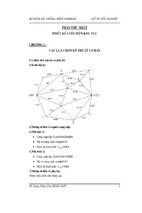
Standard Physical Topology
Addressing Scheme
Router
Interface
IP Address
R2
Loopback0
2001:2222:2222::/64
R2
Serial0/1/0.24
2001:24:24:0::/64
R2
Serial0/1/0.256
2001:256:256::/64
R4
Serial0/0/0.24
2001:24:24::/64
R4
Loopback0
2001:4444:4444::/64
R4
Loopback1
2001:4411:4411::/64
R5
Loopback0
2001:5555:5555::/64
R5
Serial0/1/0
2001:256:256::/64
R6
Loopback0
2001:6666:6666::/64
R6
Serial4/0
2001:256:256::/64
R2
R4
R5
R6
Copyright IPexpert, Inc. (http://www.IPexpert.com) 2005. All Rights Reserved.
19
IPexpert’s IPv6 eBook
Frame Relay DLCI Assignments
Router
R2 to R4
R2 to R5
R2 to R6
R4 to R 401
R5 to R2
R6 to R2
DLCI
104
105
106
501
601
IPv6 Lab Technical Tasks
A. Using an EUI-64 interface ID, configure Loopback address on R2, R4, R5, R6, as
indicated in table above.
B. R2's s0/1/0, R5's s0/1/0 and R6's s4/0 are the main FR cloud. Configure
multipoint sub-interface on R2's s0/1/0 and use physical interfaces for R5 and
R6.
C. Configure a point-to-point sub-interface for the FR connection between R2's
s0/1/0 and R4's s0/0/0.
D. Configure a host table on every router with the IPv6 address.
E. Configure a static route for R4 pointing to R5’s loopback. Change the
administrative distance to 2.
F. Configure OSPF Area 0 for R2's loopback, s0/1/0.256, R5's loopback, s0/1/0,
R6's loopback and s4/0. Use x.x.x.x as the router-ID, where x is the router
number. For example, R2 should have router-ID as 2.2.2.2.
G. Configure OSPF Area 24 for R2's s0/1/0.24, R4's s0/0/0.24 and loopback 0.
H. Configure RIP for R2's s0/1/0.24, R4's s0/0/0.24 and loopback 1.
I.
Redistribute OSPF and RIP into each other. The RIP metric after redistribution
should be 7 and the OSPF Type 1 metric should be 1000.
J.
Verify connectivity by telnetting and pinging different places.
IPv6 Lab Instructor’s Comments and Technical Tips
A. To configure an IPv6 address for an interface and enable IPv6 processing on the
interface using an EUI-64 interface ID in the low order 64 bits of the address, use
the IPv6 address EUI-64 command.
B. The Frame Relay map IPv6 command is similar to the Frame Relay map
command, except that it is IPv6-specific. The Frame Relay map defines the
logical connection between a specific protocol and address pair and the correct
DLCI.
C. None.
Copyright IPexpert, Inc. (http://www.IPexpert.com) 2005. All Rights Reserved.
20
- Xem thêm -