Practical Guideline for
Investigation, Repair and Strengthening
of Cracked Concrete Structures -2009-
Japan Concrete Institute
Practical Guideline for
Investigation, Repair and Strengthening
of Cracked Concrete Structures -2009-
Japan Concrete Institute
All rights reserved. No part of this work may be reproduced, transcribed or
used in any form of by any means-graphic, electronic, or mechanical,
including photocopying, recording, typing, Web distribution, or information
storage and/ or systems-without the prior written permission of the Japan
Concrete Institute.
Preface
In spite of numerous efforts to eliminate cracks from concrete structures, there
are still many cracked concrete structures. Some cracks are very harmful and should be
repaired as soon as possible, while other cracks are almost harmless. Therefore, a good
guideline on how to deal with cracks in concrete structures has long been needed. JCI
published “Practical Guideline for Investigation and Repair of Concrete Structures” in
1980, a second version followed in 1987, and a third version was followed in 2003. In
this third version, English edition was also published. Then in 2009, A fourth version
was published in Japanese in 2009. This volume, titled “Practical Guideline for
Investigation, Repair and Strengthening of Cracked Concrete Structures -2009-“ is the
English edition of this latest version. It is believed that this guideline will be much use
when cracks are detected in existing concrete structures, both in Japan and overseas.
Contents
Chapter 1 General ··········································································································
1
1.1 Scope and Objective ············································································································
1
1.2 Procedure from Investigation to Repair and Strengthening ··············································
2
1.3 Terms and Definitions ·········································································································· 11
Chapter 2 Investigation ································································································
11
2.1 General ································································································································· 11
2.2 Standard Investigation ········································································································ 11
2.3 Detailed Investigation ········································································································· 25
Chapter 3 Cause Estimation······················································································
44
3.1 General ································································································································
3.2 Cause of Cracking ···············································································································
3.3 Cause Estimation Based on Standard Investigation ··························································
3.4 Cause Estimation Based on Detailed Investigation ····························································
44
44
45
76
Chapter 4 Evaluation of Cracks ··············································································
79
4.1 General ································································································································
4.2 Evaluation-I (Applied for Cracks due to Drying Shrinkage, etc.) ·····································
4.3 Evaluation-II (Applied for Cracks due to Carbonation and Chloride Attack, etc.) ··········
4.4 Evaluation-III (Applied for Cracks due to Combined Deterioration, etc.) ·······················
79
84
86
94
Chapter 5 Judgment of Necessity of Repair and Strengthening ············
96
5.1 General ································································································································ 96
5.2 Methods of Judgment ········································································································· 97
Chapter 6 Repair and Strengthening ···································································· 101
6.1 General ································································································································ 101
6.2 Design of Repair and Strengthening ··················································································· 102
6.3 Repair Methods ····················································································································111
6.4 Strengthening Methods ······································································································· 124
6.5 Repair and Strengthening Materials ·················································································· 143
6.6 Repair and Strengthening Works ······················································································· 151
6.7 Inspection ···························································································································· 154
6.8 Records and Interim Observations····················································································· 155
Practical Guideline for Investigation, Repair and Strengthening of Cracked Concrete Structures -2009-
1
Chapter 1 General
1.1 Scope and Objective
(1) This Guideline covers the practicable investigations of cracked concrete members or structures,
cause estimation, evaluation, judgment of the necessity of repair or strengthening, selection of the
most effective repair and strengthening method, and the case studies. This Guideline applies mainly
to cast-in-situ concrete structures.
(2) This Guideline covers the cracks generated in a concrete member or structure after casting and
during the service life.
(3) The main users of this guideline are the owners including managers of the concerned structures as
well as engineers who are working for investigation, cause estimation, evaluation, judgment, and
repair or strengthening of cracked concrete structures.
[Comments]
(1) and (2)
1) Targeted concrete members or structures
This Guideline mainly covers the common cast-in-situ reinforced concrete and prestressed concrete
structures which include buildings, bridges, pavements, concrete dams, etc. This Guideline does not
cover the precast reinforced concrete structures. However, it can be used for such structures with certain
limitations and restrictions. Engineers assigned to judge such structures must be specially trained and
have advanced knowledge in this area.
2) Targeted cracks
This Guideline covers the cracks which are developed in concrete members or structures after casting of
concrete. The causes of cracking covered by this Guideline are summarized in Table 3.1.
Countermeasures can be adopted during the design stage of concrete members or structures. This
Guideline does not cover the countermeasures adopted in the design stage. The normally recommended
items and methods for cause estimation of cracking, evaluation, judgment on the necessity for repair
and strengthening and appropriate technical methods for repair and strengthening are explained in this
Guideline.
This Guideline does not deal with all conditions such as various types of structures, influences on third
party, exposure conditions, etc. This Guideline can be used as a basic tool to judge how to evaluate the
condition of structures, how to evaluate the causes of cracking, and what to do if repair and
strengthening are necessary. Therefore, when this Guideline is applied, it is necessary to plan practical
countermeasures taking into consideration of the various conditions such as its own unique environment,
service loads, etc.
3) Technical contents
The main users of this Guideline are from a beginner to a middle career engineer who is in-charge of a
structure for maintenance and taking actions if there are cracks in the structures or concrete members.
Therefore, this Guideline is prepared in a simple way for easy learning and application of the learned
knowledge in concerned structures. This Guideline systematically described the process of investigation
(Chapter 2), cause estimation (Chapter 3), evaluation (Chapter 4), judgment (Chapter 5) and repair
and strengthening (Chapter 6). Moreover, examples are compiled in this Guideline that can be used as
useful references by the engineers with a little professional experience in this field.
4) Necessity for re-investigation
Crack widths generally fluctuate with service loads, seasonal change and age of the structure. Therefore,
judgment may differ based on the time of evaluation. Even if a structure is judged not to do repair based
on the result of investigation of the present condition of the structure, re-investigation is necessary in the
future and appropriate measures may be adopted based on the future investigation. Therefore, a
periodical investigation is to be suggested for the important concrete members or structures even though
any repair actions are not necessary at the present condition. In such a case, it is wise to suggest
2
Practical Guideline for Investigation, Repair and Strengthening of Cracked Concrete Structures -2009-
re-investigation, evaluation, judgment and selection of a repair and a strengthening method based on the
evaluation and the judgment in future.
(3)
1) The main users of this Guideline
The intended users of this Guideline are owners, managers, and beginner to mid-level engineers who are
assigned for examining the structure or concrete members.
Therefore, this Guideline is prepared in a simple way so that the users can gain the knowledge of the
subject and apply the learned knowledge in practice. If a user cannot understand some parts or has some
doubts, he/she should ask expert engineers for help.
This Guideline assumes that the beginner is a person who does not have practical experiences regarding
crack-related problems of concrete, such as a resident who discovers cracks in concrete members in
his/her apartment building and a municipality official who is just nominated as a maintenance engineer
of concrete structures.
2) Limit of this Guideline
As stated earlier, this Guideline is prepared in a simple and understandable way for a series of acts from
the investigation to the selection of the repair and strengthening of a crack so that the beginner to the
mid-level engineers who are engaged with the maintenance of concrete structures can easily use it. But,
when it is not possible to deal only by this Guideline, the judgment of an expert engineer who has
advanced knowledge and the experience in investigation, repair, and strengthening of concrete
structures is needed.
1.2 Procedure from Investigation to Repair and Strengthening
A flow diagram of the general procedure from investigation to repair and strengthening of concrete
structures with cracks is shown in Fig. 1.2.1.
Identification of crack
Standard inves tigation for
caus e es timation (2.2)
Detailed inves tigation for
caus e es timation (2.3)
Can it be es timated
the caus e of cracking?
No
Yes
The caus e es timation (3.3)
[W hen detailed inves tigation was conducted
(3.4)]
Selection of type of es timation (4.1)
Inves tigation for evaluation
(W hen it is neces s ary)
Evaluation (4.2)(4.3)(4.4)*
Judgement (5)*
Repair and s trengthening
(6)
Additional inves tigation for
repair and s trengthening
(6.2.3)
(Mainly, inves tigation s
uch
as cons truction environment,
amount and range, etc.)
Note1) A parenthes is ( ) in the flow means number of
chapter or s ection.
Note2) An as teris k * in the flow means that the
evaluation and judgment method are different
by the s election of Evaluation-I, Evaluation-II
and Evaluation-III.
Fig. 1.2.1 Procedure from the investigation of cracks to the application of repair or strengthening
Practical Guideline for Investigation, Repair and Strengthening of Cracked Concrete Structures -2009-
3
[Comments]
The procedure from investigation to repair and strengthening in this Guideline is shown in Fig. 1.2.1.
Strictly, this procedure could not correspond to some cracks while this flow diagram shows a standard
procedure that can correspond to most of the cracks. When cause estimation, evaluation, judgment and
selection of repair and strengthening methods are difficult, it is preferable to receive advice from
professional engineers who have advanced knowledge and experiences.
1) Identification of the crack
A series of repair and strengthening begins upon identification of cracks in a structure. Thus, the
identification of crack shown in Fig. 1.2.1 is defined when some actions are intended to consider against
the crack.
2) Standard investigation and detailed investigation
The investigation is classified into “a. investigation for cause estimation” as a principal objective of
investigation and “b. additional investigation for evaluation and repair/strengthening design.” The
methods and the principles of standard investigation and detailed investigation are described in 2.2 and
2.3, respectively.
a. Investigation for cause estimation
After crack identification, standard investigation for cause estimation of the crack is executed first.
Sometimes the cause estimation might be possible only by the result of standard investigation. However,
when the information obtained from standard investigation is insufficient, detailed investigation
including nondestructive tests, minor destructive tests, coring, destructive tests, laboratory test, etc. is
required. When a crack is estimated to be caused by alkali aggregate reaction, frost damage and
chemical attack, detailed investigation for evaluation might become necessary in order to obtain further
information on degradation of a concrete member or structure.
b. Investigation for evaluation and repair/strengthening design
Sometimes all the information necessary for repair/strengthening design might be able to be covered by
a. However, additional investigation is often needed to specify the environment at site and amounts of
the repair/strengthening.
3) Cause estimation
In this Guideline, first of all, the cause of cracking is estimated from the result of standard investigation.
When it is judged that the information collected by standard investigation is insufficient for cause
estimation, detailed investigation is carried out for adding further information for precise estimation.
When the causes are still unclear, advice from expert engineers may support the estimation.
4) Evaluation
After completing the cause estimation, the influence of cracking on structural performance of a concrete
member or structure is evaluated. That is, the evaluation in this Guideline is objectively conducted
based on the result of investigation and the estimated causes. For this purpose, the evaluation should be
done taking into account the influences of cracks on required performance of a member or structure at
present and in the future. Therefore, in this Guideline, proper methods of evaluation should be selected
based on the estimated causes of cracking. The classification of the evaluation methods is described in
4.1.
5) Judgment
Judgment is conducted in consideration of the result of evaluation, economical conditions, social
importance of structure, etc. When judgment is made according to this Guideline, the owner or the
manager of the structure is required in advance to specify required performance of the structure or
member at present and in the future, an expected remaining service life by the owner, social importance,
budget allocation for repair and strengthening, etc.
For instance, repair or strengthening is not necessary if the cause of cracking is clearly estimated and the
evaluation results indicate that structural performance might not be degraded over a long period of time
(compared with the expected remaining service life). Conversely, if evaluation results conclude that
4
Practical Guideline for Investigation, Repair and Strengthening of Cracked Concrete Structures -2009-
structural performance would be degraded below the required levels within a short term (in the near
future from the identification of the crack), repair or strengthening is necessary. In case of budget
restriction, some countermeasures might be selected, such as an increase in frequencies of investigation,
repair for aesthetic purposes, limitation of services, change in use, demolition/removal, etc.
6) Repair and strengthening
Design and execution of repair and strengthening are done in consideration of the estimated cause of
cracking, the evaluation and judgment results, etc. Repair and strengthening methods are preferably
selected based on the life-cycle assessment, asset management as well as the prediction of future
deterioration of concrete member or structure.
1.3 Terms and Definitions
The technical terms used in this Guideline are defined as follows:
(1) Investigation: action to grasp the current state of concrete members (structures) and to collect the
definite data on concrete members (structures) and cracks.
(2) Evaluation: action to objectively grasp the influence of the targeted cracks on the performance of
concrete members (structures) at the present and in the future.
(3) Judgment: action to decide the necessity of repair and strengthening according to the influence of
the targeted cracks on the performance of concrete members (structures) as well as special
limitation, such as importance of structure, which is obtained as the results of evaluation.
(4) Repair: action taken for recovering the performance of degraded (deteriorated and/or damaged)
structures by cracks. The main objectives of repair are to reduce water and air permeability, to
control the rate of corrosion, to improve the aesthetic view, etc. Strengthening of concrete or
structural members is not covered in repair.
(5) Strengthening: improvement of structural performance such as the load carrying capacity etc. to a
desired safe level.
(6) Crack width: opening width on the surface of the structure normal to the direction of the crack.
(7) Initial defect: cracks, honeycomb, cold joint, etc. generated during construction. These are the
construction defects.
(8) Deterioration: changes in material performance with time after hardening of concrete due to the
some changes in concrete itself or by cracks due to corrosion of steel in concrete.
(9) Damage: cracks or spalling generated on the surface of concrete caused by an earthquake or impact
for a short period of time.
(10) Degradation: a term that covers initial defect, damage and deterioration.
(11) Expert engineer: An engineer having advanced knowledge and experience on concrete technology
and diagnosis of damaged concrete structure. In Japan, “concrete inspectors” and “professional
concrete engineers” are certified by the Japan Concrete Institute (JCI).
(12) Owner: owner or manager of the structure.
(13) Residual period: residual period that the concrete member or structure could satisfy the required
performance from the time of investigation of the crack, evaluation, judgment, repair and
strengthening.
(14) Remaining service life: residual life to reach the design service life from the time of investigation
of the crack, evaluation, judgment, and repair and strengthening.
(15) Expected remaining service life: residual life which is expected by the owner to use the concrete
member or structure from the time of investigation of the crack, evaluation, judgment or repair and
strengthening.
(16) Minor destructive test: an examination to measure the strength of concrete using the collected
samples by partially destroying the structure.
[Comments]
In this Guideline, the following technical terms are defined. The other technical terms used in a
particular section are defined there accordingly.
Practical Guideline for Investigation, Repair and Strengthening of Cracked Concrete Structures -2009-
5
(1) In this Guideline, “investigation” is defined as a technical and objective action and “inspection” as
an administrative and subjective action. That is, investigation includes technical contents, such as what
tests should be performed and what should be measured, etc, while inspection includes administrative
and businesslike contents, such as who is the person in charge and what items should be inspected, etc.
Since the inspection of this Guideline is defined as the action to grasp the current state of concrete
members or structures and generic term of the action to investigate whether there are some defects or
not in the targeted structure, sometimes investigation is included in inspection.
(2) In this Guideline, “evaluation” is defined as an objective action to grasp the influence of cracking on
the performance of concrete members or structures at the present and in the future by using the results
of investigation and cause estimation in order to perform the technical judgment from the cause
estimation of cracking to the judgment of the necessity of repair and strengthening. Moreover, the
evaluation methods can be classified into the following three types:
1) Evaluation-I (applied for cracks due to drying-shrinkage, etc.)
Evaluation-I is applicable to the cracks that stop spreading within several years after casting, such as
drying-shrinkage cracks and thermal cracks etc. The evaluation can be conducted by investigating the
documents and also investigating the current state of concrete members or structures. In general, this
evaluation is applicable to a case when the structural performance is able to keep over requirements by
repair during the remaining service life or the expected remaining service life by the owner. When
Evaluation-I is applied, a crack width at the time of investigation or repair can be evaluated taking into
account durability against corrosion of steel bar, water tightness and environmental conditions, etc. The
criteria of the crack width for Evaluation-I are specified in 4.2.
2) Evaluation-II (applied for cracks due to chloride attack, carbonation, etc.)
Evaluation-II should be applied for the cracks which progress with time, such as the cracks due to
chloride attack and carbonation. Furthermore, evaluation for these cracks can be conducted with the
results of detailed investigation as well as the investigation of documents and visual observation of the
concrete members or structures.
These kinds of cracks are often discovered at several years or decades after construction. Therefore, it
may possible that the performance degradation has already been induced at the time of investigation or
repair. Moreover, since the mechanisms and the factors of the cracks are different depending on the
causes, these kinds of cracks should be evaluated by understanding the performance degradation at the
time of investigation, repair or strengthening, and considering the remaining service life or the expected
remaining service life by the owner. The standard evaluation criteria are specified in 4.3 according to
the causes of cracking.
3) Evaluation-III (applied for cracks due to combined deterioration, etc.)
Evaluation-III is applied for the cracks when Evaluation-I or Evaluation-II is not applicable because the
cause of crack is due to the combined deterioration or when the verification of structural performance of
concrete member or structures is needed. This evaluation should be conducted by an expert engineer
who has the license for concrete inspection. This evaluation is applied when a long-term (more than 20
years) remaining service life or a long-term expected remaining service life by the owner is required.
Moreover a crack caused by the mechanical reasons such as changes in support or loading condition
should be evaluated by Evaluation-III.
(3) In this Guideline, judgment is conducted by considering the restrictions, such as social importance
of concrete member or structure, budget of the owner and the scenario of maintenance including the
remaining service life or the expected remaining service life, life cycle assessment and asset
management. Therefore, the judgment includes the increase in frequencies of inspection, repair for
aesthetic purpose, limitation of service, change of use, demolition etc.
(4) Cracks in concrete will degrade structural performance such as safety, influences on the third party,
serviceability, durability, etc. Repair is defined as an action to recover and improve the performance
except the load carrying capacity to their required levels (generally at least the level of the performance
6
Practical Guideline for Investigation, Repair and Strengthening of Cracked Concrete Structures -2009-
without any cracks).
(5) Repair is performed against a crack itself in order to improve the performance such as
waterproofness, while strengthening is performed against the concrete members or the structures. In this
Guideline, strengthening is defined as an action to recover and improve degraded structural performance
caused by the cross-sectional loss of steel bar and degradation of bond between steel bar and concrete
due to corrosion. Structural performance after strengthening should definitely satisfy the required
performance; for example either load carrying capacity against current load actions or load carrying
capacity due to more loads in future. Furthermore, strengthening may enhance structural performance
compared to the originally designed level.
There are two types of members in a concrete structure. One is a member to support loads acting on the
structure, which is called as a structural member, while the other is that to satisfy the non-mechanical
performance, such as fire resistance, heat insulation, water tightness, air tightness, sound insulation, etc.,
which is called as a non-structural member. Since an unexpected crack may cause performance
degradation of a concrete member or structure, examination for repair is necessary for both structural
and non-structural members. Moreover, examination for strengthening is sometimes necessary for a
structural member in addition to that for repair. When strengthening is judged to be necessary, a repair
work may be added depending on the cause of crack and the applied strengthening method. In this
Guideline, when a crack is initiated in structurally unimportant directions even in a structural member,
the same treatment as for a non-structural member may be applied.
(6) A crack width is defined as the surface opening perpendicular to the crack path. Generally, rapid
degradation is observed for a wider crack. Contrary, degradation may not be so significant during the
service life of structure for a narrower crack. Therefore, the width of crack is an important factor for
judgment on the necessity of repair and strengthening as well as selection of a suitable repair and
strengthening method. Additional notes related to the crack width are given below:
(i) The surface crack width generally varies with the depth inside concrete. A larger width is observed
on the surface and it gradually reduces with depth. The surface crack width also greatly depends on the
location of steel bar in concrete. A larger cover depth will lead to increase the crack width on the surface.
Therefore, degradation rate cannot be generalized with respect to the crack width.
(ii) Dimensional change such as shrinkage and expansion of concrete structures occurs with the
variation of temperature as well as moisture content and imposed service load over the structure. It
indicates that the crack width is not necessarily a constant value.
(iii) Multidirectional cracks can be generated on the concrete surface, therefore it may be difficult to fix
a particular direction for measuring the crack width.
(iv) The crack width may vary along the crack path.
For these reasons, it is necessary to specify the time of measurement, position, and the method of
measurement of crack width, which will be utilized to judge the present condition of the structure,
causes of cracking, and possible necessary countermeasures. In addition, the crack width for
Evaluation-I related to steel bar corrosion is the maximum on the surface of concrete at the position of
steel bar.
(7) Defects are generated in a structure during construction as well as after construction of a structure.
Defects that are generated during construction, such as cracks, honeycomb, cold joint, etc. are
particularly called as “initial defect”.
In addition, a crack caused by "A9: drying shrinkage" presented in Table 3.1 occurs after the removal of
formwork or during curing. There is a case that this kind of crack occurs during construction (several
days to several months) or several years after the start of service. Therefore, in this Guideline, the
former are classified as “initial defect” because a crack due to drying shrinkage based on the former
tends to generate due to the early removal of formwork and the insufficient curing period.
Practical Guideline for Investigation, Repair and Strengthening of Cracked Concrete Structures -2009-
7
(8) In this Guideline, “deterioration” is defined as a process which adversely affects the structural
performance, such as steel corrosion due to chloride attack and carbonation and change in properties of
concrete itself due to alkali aggregate reaction, frost damage, etc.
Moreover, as mentioned in comment (7), the cracks that occur several years after the start of service by
“A9: drying shrinkage” are classified as “deterioration” because it tends to generate when the concrete
member or structure is always exposed to drying condition and when the relative humidity around the
structure drastically decreases by weather change.
(9) In this Guideline, degradation that occurs in a short term and does not change with time, such as a
crack or peeling of concrete generated by earthquake, impact, etc. is defined as “damage”.
(10) Degradation is defined as a general term including initial defect, damage and deterioration.
(11) Judgment on the necessity of repair is comparatively easy when the cause of crack is clear and the
degradation of the structure can be observed with the naked eye, such as water leakage, deformation,
and spoiled appearance. However, a crack generated in a real structure may come in different form and
it may be difficult to find out the exact causes of cracking even after detailed investigation. In some
cases, judgment on the necessity for repair and strengthening is difficult even though degradation is
clearly observed over the surface. Therefore, in this case, judgment as to the cause of crack, the
necessity for repair/strengthening, and repair/strengthening methods, if required, must be made by an
engineer who is familiar with the subject matter and has extensive experiences in this area.
In Japan, a “concrete inspector” and a “professional concrete engineers” have been certified by the
Japan Concrete Institute since 2001 and 1971, respectively. Both categories are registered as concrete
experts. The concrete inspector is certified as having advanced engineering ability for investigation,
diagnosis, and selection of repair and strengthening strategies for the deteriorated concrete structures. A
professional concrete engineer is mainly certified as having advanced knowledge in concrete technology
and the ability to supervise the construction by ready-mix concrete and in-situ casting of concrete. Here,
the term “expert engineer” as used in this Guideline also includes persons with advanced knowledge of
concrete technology. A first-class architect and a building engineer are also included in this category. A
person with engineering knowledge and experience equal to or greater than that of concrete inspector or
professional concrete engineer can also be considered as an “expert engineer”. An engineer is always
responsible for all his/her judgments related to repair and strengthening, and must keep him/herself up
to date with the present state of the art.
(12) The owner in this Guideline is an owner or a manager of a concerned concrete structure. It is
indicated the person who can actually decide the importance of structure, budget, and necessity of repair
and strengthening. For instance, it corresponds to the management society of an apartment house or the
municipality that manages buildings, RC bridges, and so on. Here, a consulting engineer who is given
the authority of judgment and decision of technical point by the owner is also called as the owner for
descriptive purposes.
(13) Generally, the durable period of a concrete structure is set as the period that maintains the required
performance during the design service life at the planning and design stages. Therefore, it is common
that the design and construction of concrete structure are executed in such a way so that the durable
period is longer than the design service life. However, when a crack occurs due to some causes that
were not considered in the design stage and the performance of the concrete member or structure is
degraded, there is a case that is compelled to evaluate as the durable period shorter than the design
service life even if repair and strengthening is performed.
Therefore, in this Guideline, the technical term as the “residual period” is defined as the period during
which the required performance of structure can be maintained after the execution of investigation,
evaluation, judgment, and repair and strengthening.
(14) There are three concepts about the service life; one is the “design service life” that is set based on
how many years the owner wants to use the structure in consideration of the amortization period of the
8
Practical Guideline for Investigation, Repair and Strengthening of Cracked Concrete Structures -2009-
structure and social importance. The second is the “elapsed service life” that is the period for which a
structure has been actually used after construction. The third is the “remaining service life” that is the
period from the present to the design service life.
In this Guideline, the remaining service life is defined based on the judgment of the necessity of repair
or strengthening and the execution of repair or strengthening design considering the “residual period”
after investigation, evaluation, judgment, and repair and strengthening.
(15) In the other guidelines, the technical terms, such as the design service life and the residual period
are often used. Moreover, there are many descriptions assuming that the service life and the residual
period can be determined easily. However, in many cases, the inhabitants of an apartment or the owner
of a structure which was constructed a long time ago do not know the design service life at the design
stage and therefore cannot set the remaining service life. In addition, there are also cases that an owner
wants to use the structure over a design service life or make an alternation to the structure for a shorter
period than that set at design by the change of the social importance of the structure and economic
circumstances. In other words, it can be concluded that judgment and design of repair and strengthening
are performed based on the owners’ intention how long he/she wants to use the structure in the future.
Therefore, in this Guideline, the expected remaining service life is newly introduced as the period when
an owner expects to use the structure after investigation of crack, evaluation, judgment, repair or
strengthening (it is included neither the repair nor the strengthening work). It is described to perform the
judgment of necessity of repair and strengthening and the repair and strengthening based on the
expected remaining service life by the owner.
When the remaining service life can be set by using the design service life at the design stage, in the
judgment and the designing of repair and strengthening, it is necessary to choose either of the expected
remaining service life by the owner or the remaining service life. In this case, it is decided to conduct
the judgment and the design of repair and strengthening based on a period by the judgment of the
owner.
The concepts of repair and strengthening designs are shown in Figs. C.1.3.1 and C.1.3.2, respectively. It
is very important for design of repair and strengthening to define the level of performance, such as
safety, serviceability and durability necessary for the structure, to grasp the performance of the structure
at the time of investigation of crack and adequately to decide the level of performance to recover by
repair and strengthening and the duration of the effects of repair and strengthening. In addition,
considering the lifecycle of the structure, it is important to conduct sufficient examination considering
that it is possible to conduct the reasonable maintenance not only by one time of repair but also by
multiple repair.
(16) A minor destructive test is an examination to perform to get information, such as compressive
strength, carbonation depth, chloride content in concrete, residual expansion by alkali aggregate reaction,
etc. by destroying a part of the structure and by using the collected samples from the structure.
Practical Guideline for Investigation, Repair and Strengthening of Cracked Concrete Structures -2009-
9
The Investigation, evaluation,
judgment or execution of repair
Service start
Design service life
Remaining service life
Elapsed service life
Expected remaining service life
Residual period on serviceability etc.
when a repair is executed.
Repair*
Serviceability etc.
When a repair is
executed one time
When crack occurs
and repair is not
executed.
Required level of
performance
Residual period on
serviceability etc.
when a repair is not
executed.
Elapsed year
Residual period on the safety performance when
repair is executed.
Safety performance
Required level of
performance
Repair*
When a repair is
executed one time
When crack occurs
and repair is not
executed.
Residual period on the
safety performance
when a repair is not
executed.
Elapsed year
* When repair is executed, the performance such as waterproof or the aesthetic can be recovered or
improved, while the safety performance such as the load carrying capacity cannot be recovered or
improved. However, the period that the concrete member could satisfy the various performances can be
extended (the durability is recovered or improved).
Fig. C.1.3.1 Concepts of design for repair (only one repair during a life time)
10
Practical Guideline for Investigation, Repair and Strengthening of Cracked Concrete Structures -2009-
Service start
The Investigation, evaluation,
judgment or execution of
strengthening (repair)
Design service life
Remaining service life
Elapsed service life
Expected remaining service life
Residual period on serviceability etc.
when a strengthening (including repair)
is executed.
Strengthening*
Serviceability
etc.
Required level of
performance
When crack occurs
and strengthening (or
repair) is not
executed.
When a strengthening
(including repair) is
executed.
Residual period on
serviceability, etc when a
strengthening (or repair)
is not executed.
Elapsed year
Residual period on the safety performance
when strengthening (including repair) is
executed.
Strengthening*
Safety performance
Required level of
performance
When crack occurs
and strengthening (or
repair) is not
executed.
When a strengthening
(including repair) is
executed.
Residual period on the
safety performance when a
strengthening (or repair) is
not executed.
Elapsed year
* When strengthening is executed, the mechanical performance such as load carrying capacity can
be recovered or improved, and the performance such as water tightness, the aesthetic can be also
recovered or improved by a combination with suitable repair. Besides, the period which the concrete
member could satisfy the various performances can be extended (the durability can be recovered or
improved).
Fig. C.1.3.2 Concepts of design for strengthening
Practical Guideline for Investigation, Repair and Strengthening of Cracked Concrete Structures -2009-
11
Chapter 2 Investigation
2.1 General
(1) The main objective of investigation is to collect data for the estimation of the causes of cracking of a
structure or its members. These data are also necessary for subsequent evaluation of cracks,
judgment of the necessity of repair and strengthening.
(2) There are two types of investigation, such as standard investigation and detailed investigation.
[Comments]
(1) Investigation described in this chapter is the beginning step for cause estimation, evaluation of
cracks and a selection of repair and strengthening. Information based on the appropriate investigation
enables not only to predict the causes of cracking but also to select suitable methods of repair and
strengthening. This Guideline recommends identifying the causes of cracking before selection of a
repair and strengthening method. Hence, cause estimation of cracking plays a significant role in this
Guideline. Furthermore, the investigations proposed in this chapter are useful for evaluation of cause of
cracks, repair and strengthening.
(2) In this chapter, "investigation" is divided into two steps, such as "standard investigation" and
"detailed investigation." Standard investigation must be carried out as the preliminary investigation. The
detailed investigation should be carried out in the case that cause estimation of cracking, repair and
strengthening cannot be performed based on the standard investigation. Table C.2.1.1 shows a list of
investigation methods proposed in this Guideline. The applicable grades of each testing method are
classified as ~, { and U for the cause estimation, evaluation of cracks, repair and strengthening.
2.2 Standard Investigation
(1) Standard investigation is carried out by investigating the documents and visual inspection of
structures.
(2) Investigations of documents and observation of structures should include the following items:
1) Investigation of documents
a. Engineering drawings, design reports and specifications (drawings, steel bar arrangement,
structural calculation results, etc.)
b. Construction record such as materials used, mixture proportion, placing, curing method,
construction schedule, sub-soil investigation report, formwork, weather condition during
placement of concrete
c. History of the past investigation, repair and strengthening (maintenance record of structure,
records of repair and strengthening, renovation, claim, etc.)
d. Service load condition (conditions at design and at present)
e. Climate condition (temperature, relative humidity, wind velocity, wind direction, height of
wave, direction of wave, air pressure, etc.)
f. Geological condition (distance from the sea, existence of harmful agents, such as de-icing
agents, snow melting agents, etc.)
g. Ground condition (vertical distance to the adjacent structures, conditions of retaining wall,
foundation, etc.)
2) Visual observation of structures
a. Investigation of the condition of the cracks (such as crack width, crack length, crack area,
crack pattern, existence of penetrating crack, etc.)
b. Investigation of other phenomena occurred due to the cracks (peeling of concrete cover and
finishing materials, honeycomb, pop out, efflorescence, etc.)
c. Investigation of inconveniences due to cracks (moisture leakage, corrosion of steel bars,
deflection of structural members, appearance, etc.)
d. Investigation of unusual vibration (at driving and at walking)
a
Chapter
e
Ite s
Chap 2 ,nYestLgatLon
or investigation
art
Items of inspection
Type of investigation
S
t
a
n
d
a
r
d
I
n
v
e
s
t
i
g
a
t
i
o
n
D
o
c
u
m
e
n
t
r
e
s
e
a
r
c
h
Engineering
drawings
Collection of
records,
confirmation of site
and hearing
Drwings, re-bar arrangement, structural
calculation, test results of materials
used, specifications, etc.
Document to be researched
Drying
shrinkage
Way to use of results(※2)
Repair and strengthnening
EvaluationII EvaluationIII
(Carbonation,
salt damage,
ASR frost
damage,
chemical
corrosion etc.
(Stractural
crack),(extre
me defect,
composite
deterioration
etc.)
Cause
estimation,
evaluation
○
○
○
○
Data of materials (cement, aggregate,
mineral and chemical additives mixing
Construction water),mixture proportions,casting,
curing, plan, quality control data,
Cinfirmation of ducument
records
condition of soiul, environmental
condition at casting, weather condition,
etc
○
○
○
○
Investigation,
history of
repair and
strengthening
○
○
○
Cinfirmation of ducument, visual inspection, hearing
○
○
○
Cinfirmation of ducument, map, visual inspection,
feeling, hearing
○
○
○
Past investigation, repair and
strengthening, renovation, dakage, claim, Cinfirmation of ducument
records at finding of crack
Confirmation that present load condition
Condition of
does ont exeed the load condition at
service load
design
Weather,
condition of
sea,
environment
and
foundation
Temperature, himidity, CO2
consentration, swoop salinity, chemical
component, distance from sea, existence
of de-icing agent, snow melting agent,
cold area nor not, spring area or not,
vibration,soft ground or not
Type of investigation
Items of inspection
State of
ctacks
peeling and
flaking
Visual inspection of
structure
Hunycomb
Water leakage
Test methods, equipments
Drying
shrinkage
Width
Visual inspection, scale, crack scale and microscope
Length, total length
Visual inspection, scale, digital camera
Position, area
Visual inspection, scale, digital camera
Pattern
Visual inspection, digital camera
Difference in level
Visual inspection, scale
Penetration
Visual inspection, scale
Position and area of peeling of concrete
coverand finishing
Visual inspection, test hammmer, scale
Position and area
Visual inspection, scale
○
Position and area
Visual inspection, scale
○
Visual inspection, scale
○
Visual inspection
○
Change of
Position and area
color,
Depositionio Color
Popout
Visual inspection, scale
n cold joint Position and area
Unusual sound, inconvenience, vibration
at driving and walking, inconvenience of Feeling,phone,visual inspection, scale
Unusual
fittings
feeling
Position
Feeling,phone,visual inspection, scale
○
(Carbonation,
salt damage,
ASR frost
damage,
chemical
corrosion etc.
○
○
-
○
-
Way to use of results(※2)
Repair and strengthnening
Cause
estimation,
evaluation
Estimation
ning
○
○
○
○
○
○
○
○
○
○
○
○
○
○
○
○
○
○
○
○
○
○
○
○
○
○
○
○
○
○
○
○
○
○
○
○
○
○
○
○
○
○
○
○
○
○
○
○
○
○
○
○
○
○
○
Note
Selection
Judgment for
Examination
of repair
of material
necessity of
of execution
and
repair and
and
date
strengthne
strengthening
method
○
○
-
-
○
EvaluationIII
(Stractural
crack),(extre
me defect,
composite
deterioration
etc.)
○
-
Type of evaluation(※1)
EvaluationII
Note
ning
Cinfirmation of ducument
Evaluation
I
n
s
p
e
c
t
i
o
n
Estimation
Judgment for Examination Selection of repair
necessity of
of material
of execution
and
repair and
and
date
strengthne
strengthening
method
○
○
○
○
○
○
○
○
Classification based on fihure of crack pattern
Rekation to environmental condition and ground
condition
Comarison with crack width limit
Criteria of judgement for necesstity of repai and
strengthening
Classification based o
○
○
Judgement for necesstity of repai and strengthening
Rekation to environmental condition and ground
condition
○
○
Judgement for necesstity of repai and strengthening
Rekation to environmental condition, servicebility
performance and ground condition
1:○Special needs for investigation. In the case of extreme deterioration and composite deterioration in Evaluation III,there will be needs for investigation.
2: ,○, in order of importance for investigation.
12
Type of evaluation(※1)
Evaluation
Chap 3 Cause estLmatLon of cracks
Chap 4 (YaOuatLon
Chap 5 Judgment for necessLty of
repaLr and strengthenLng
Chap 5 Judgment for necessLty of
repaLr and strengthenLng
Chap 6 5 e p a L r a n d
stregnthenLng
Chap 3 Cause estLmatLon of cracks
Chap 4 (YaOuatLon
a le
investigation
Chapter
te s
a t
Chap 2 ,nYestLgatLon
o
Chap 3 Cause estLmatLon of cracks
Chap 4 (YaOuatLon
Way to use of results(※2)
Type of evaluation(※1)
Evaluation
Type of investigation
Items of inspection
Crack progress
Visual inspection, crack scale, microscope, π-type
dispacement gauge, contact type gauge, degital camera,
acoustic emission, laser method
Position, depth and area of peeling and
flaking of concrete cover and finishings
Sampling of core and thermographic method
Estimation of strength
Concrete
D
e
t
a
i
l
e
d
i
n
v
e
s
t
i
g
a
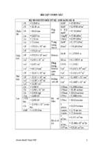
t
i
o
n
Nondestructive
, minor
destructive
test and
test with
core
specimen
O
n
s
i
t
e
i
n
v
e
s
t
i
g
a
t
i
o
n
Steel bar
Investigat
ion of
innrr
part/quali
ty of
structure
Degree of quality
Homogeneity
foundation condition of
Foundation
structure
Investigation of
vibration of structure
Structure,
member
○
○
○
○
○
○
○
○
○
○
○
○
○
Crack depth
Sampling of core and ultra sonic method
○
Cover thickness
○
○
○
Radar method, impact elastic wave method and ultrasonic
method
○
○
Position of steel bar, bar arrangement and bar diameter
Radar method, electro magnetic reasonance method,
ulutrasonic method,X-ray transmission method
○
○
Corrosion rate
half-cell potential
○
polarization resistance
X-ray transmission method, impact elastic wave method,
CCD camera
Tracer method,thermographic method (visual inspection is
impossible)
○
○
Visual inspection and phenolphthalein method
Crack depth
Deposition
Visual inspection and scale
Visual inspection
○
○
○
○
○
○
○
○
○
○
○
○
Confirmation of existence
○
○
○
○
Comparison to cover thickness
Comparison to engineering drawings and construction
record. Comparison to carbonation depth
Comparison to engineering drawings and construction
record.
○
○
○
Classfiying with corrosion rate, judgment for necessity of
repair and strengthening
○
○
○
○
○
○
Position and amount of insufficient grouting
○
○
Exisitence, amount and route of leakage
○
○
○
○
○
Comparison to engineering drawings and construction record.
○
○
○
Classification to corrosion rate, judgment for necessity
of repair and strengthening
○
○
○
record.
○
Comparison to cover thickness, estimation carbonation progress
and confirmation of consentration of chloride ion in concrete
Comparison to cover thickness
Confirmation of existence of Deposition
○
○
record.
Comparison to engineering drawings and construction
Comparison to engineering drawing and carbonation
depth
○
○
Comparison to engineering drawings and construction
Comparison to specified value, comparison of crack and failure
○
○
○
Comparison to cover thickness,comparison between
member thickness of sound area and design thickness
○
○
○
○
○
○
○
○
○
○
○
○
○
○
○
○
○
○
Classfiying on corrosion velocity
○
○
Comparison to construction record.
○
Sign of ASR
○
○
○
○
○
○
○
○
○
○
○
○
○
○
○
○
○
○
Measurement of temperature and R.H., consentration of
CO2,swoop salinity and other chemical component
Settlement of foundation, differential
settlement
Visual inspection by excavation, surveying, surface wave,
electro magnetic wave method and elastic wave method
Eccentric earth pressure
Visual inspection by excavation, surveying, surface wave,
electro magnetic wave method and elastic wave method
Side displacement
isual inspection by excavation and surveying
Inveswtigation of live load, traffic, cargo handling, load
test(oil pressure jack and actual live load), stress
frequency
○
Stiffness
○
Test by actual dynamic vibration
Vibration with shaking machine and with impact load using
falling weight
Vibration with shaking machine and with impact load using
falling weight
○
○
Degree of reduction of stiffness of structure
Comparison to standard criteria
Relation to immerging velocity of aggressive component
Comparison to design value
Judgment for necessity of repair and strengthening
○
Environmental condition which affect
deterioration around structure
Influence of load at driving and usage of
vehicle
Influence of earthquqke
○
○
○
Visual inspection and phenolphthalein method
Type of aggregate (river stone, crushed
Visual inspection
stone etc.)
exsistence of shell(exsistence
of sea sand)
Visual
inspection
Maximum size
Visual inspection and scale
Existence of reaction rim
Visual inspection
Existence of crack of coarse aggregate
Visual inspection
Existence of water leakage
Visual inspection
Existence of impurities
Visual inspection
○
○
Scale and micro scale
Visual inspection
Scale
Visual inspection, inspection mirror, R-type gauge
Visual inspection and scale
○
○
○
○
○
○
○
○
○
○
○
Carbonation depths and Margin from cover
depth to carbonation depth
○
○
○
Judgment for necessity of repair and strengthening
Relation with environmental and ground conditions
Comparison to design strength
○
○
○
Visual inspection, scale
Note
○
Confirmation of existence, amount and route
Comfirmation of existence and impurities
Comparison between design value and estimated value
○
○
○
○
○
○
○
○
○
○
○
○
○
○
○
Relation between the differential settlement,eccentric
earth pressure and side displacement and the foundation
Stability of structure as a whole
Comparison between design value and estimated value,
deflection and deformation of member, strain of concrete
and steel, settlement and slant and displacement of
foundation
Confirmation of stress frequency and Judgment based
onspecific frequency anddecay constant
1:○Special needs for investigation. In the case of extreme deterioration and composite deterioration in Evaluation III,there will be needs for investigation.
2: ,○, in order of importance for investigation.
13
Investigation of
Structure,
structural capacity and member
deformation
○
○
Diameter of steel bar
Types of steel bar (round type, deformed
type)
Spoacing of steel bar
Condition of bended zone
Cover thickness
Estimation
Judgment for Examination Selection of repair
necessity of
of material
of execution
and
repair and
and
date
strengthne
strengthening
method
ning
○
Chemical corrosion
Environment
Cause
estimation,
evaluation
○
Corrosion rate of steel
Environmental
condition of structure
(Stractural
crack),(extre
me defect,
composite
deterioration
etc.)
○
○
Water leakage
Others
(Carbonation,
salt damage,
ASR frost
damage,
chemical
corrosion etc.
○
ultrasonic method, impact elastic wave method,
thermographic method, test hammmer
Others
Aggregate
Repair and strengthnening
EvaluationII EvaluationIII
○
Internal crack and voids
Insufficient grouting
Concrete
○
Size and thickness of member
Corosion velocity
Destruct
ive test
Strength test by rebound hammmer method, ultrasonic
method, pull-out method, impact elastic wave method and
with small core
ultrasonic method, impact elastic wave method
Thermographic method and ultra sonic method
Drying
shrinkage
impact elastic wave method , radar method and ultra sonic
method
PC tendon
Steel bar
Document to be researched
Chap 3 Cause estLmatLon of cracks
Chap 4 (YaOuatLon
Chap 5 Judgment for necessLty of
repaLr and strengthenLng
Chap 5 Judgment for necessLty of
repaLr and strengthenLng
Chap 6 5 e p a L r a n d
stregnthenLng
a le
Chapter
te s
Chap 2 ,nYestLgatLon
o
investigation
a t
Chap 3 Cause estLmatLon of cracks
Chap 4 (YaOuatLon
Evaluation
Type of investigation
Items of inspection
Compressive strength
i
n
v
e
s
t
i
g
a
t
i
o
n
Phisical test
t
e
s
t
c
l
a
s
s
i
f
i
c
a
t
i
o
n
Analysis of
chemical
composition
t
e
s
t
m
e
t
h
o
d
s
(Stractural
crack),(extre
me defect,
composite
deterioration
etc.)
○
○
○
Elastic modulus
Strain measurement with wire strain gauge and
diplacement meter meted(JIS A 1149)
○
○
○
Poisson's ratio
Strain measurement with wire strain gauge and
diplacement meter meted
○
○
○
Carbonation depth
Phenolphthalein methodJIS A 1152),differential
thermal analysis,a Powder X-ray Diffractometer and
EPMA
○
○
○
Migration of chloride ion due to carbonation
Potential difference titrationwith electro node of
silver chloride, Mercury( ) thiocyanate
absorptiometry, silver nitrate titrationmethod, ion
chromatographmethod(JIS A 1154,JCI-SC4,JCI-SC5)
andEPMA
○
Chemical corrosion depth
EPMA
○
Content of chloride
Potential difference titrationwith electro node of
silver chloride, Mercury( ) thiocyanate
absorptiometry, silver nitrate titrationmethod, ion
chromatographmethod(JIS A 1154,JCI-SC4,JCI-SC5)
○
Cause
estimation,
evaluation
Estimation
Note
Judgment for Examination Selection of repair
necessity of
of material
of execution
and
repair and
and
date
strengthne
strengthening
method
ning
Comparison to design strength
Comparison to value of sound concrete and
standard value
○
Comparison to value of sound concrete and
standard value
○
Comparison to cover thickness
Comparison to estimated value of carbonation
progress
○
Migration of chloride ion due to carbonation
Chloride consentration at steel bar
○
○
Comparison to cover thickness
Regulation of JIS A 5308, comparison to steel
corrosion criteria
Potential difference titrationwith electro node of
silver chloride, Mercury( ) thiocyanate
Migration of chloride
Judgment based in chloride consentration at
concrete cover and distribution
absorptiometry, silver nitra
chromatographmethod(JIS
andEPMA
Alkaline content
Atomic spectrophotometry
○
○
○
○
Possibility of expansion due to ASR
Chemical composition analysis, a Powder X-ray
diffractometer, SEM-EDX,
method, differential therma
uranyl fluorescent method(
Analysis of Deposition
a
c
c
o
r
d
i
n
g
t
o
Way to use of results(※2)
Repair and strengthnening
EvaluationII EvaluationIII
(Carbonation,
salt damage,
ASR frost
damage,
chemical
corrosion etc.
Compressive strength test(JIS A 1107,1108)
(
D
e
t
a
i
l
e
d
L
a
b
o
r
a
t
o
r
y
Document to be researched
Drying
shrinkage
14
Type of evaluation(※1)
Chap 3 Cause estLmatLon of cracks
Chap 4 (YaOuatLon
Chap 5 Judgment for necessLty of
repaLr and strengthenLng
Chap 5 Judgment for necessLty of
repaLr and strengthenLng
Chap 6 5 e p a L r a n d
stregnthenLng
Estimation of mixture proportion
(water, w/c, unit content of cement, content of
additive, unit content of aggregate and impurities)
Microstructural
analysis
○
Quantification of OH in co
○
○
○
Judgment based on OH consentration in pore
solution
Method by J
proportion of herdened concrete(F18)」
○
○
○
Air-void spacing factors
○
○
○
Air content
Linear traver
○
○
○
Pore size distribution
Mercury intru
○
○
○
○
Erosion depth from surface
Visual inspec
○
○
Carbonation progress velosity
Accelerated
○
Rapid chlorid
○
Immerging velosity of chloride
)
Remaining expansion ratio(ASR)
Storage method at more than 40 andR.H.95%
(JCI-DD2),Immerging method at 80 ,1mol/l
NaOH(Canadamethod),Immerging method at 50
andsaturated NaCl(Denmark method)
○
Investigation of used aggregate type and reactive
mineral
Visual inspection, polarized light microscopy,a
Powder X-ray diffractometer(JCI-DD3)
○
Comparison to engineering drawings and
construction record
○
「Test of ce
Sodium gluco
2002)
Linear traver
Acceleration test
Petrology test
-
-
Estimation of expansion due to ASR
Detection of composition of Deposition
○
Judgment based on content, spacing and diameter of
air void
○
○
○
○
○
○
Classification of corrosion rate
Comparison to estimated value of carbonation
progress
Comparison to estimated value of chloride
percolation
Comparison between remaining expasive ratio and
criteria
Comfirmation of exisitence of risk of reactive
minaral
1:○Special needs for investigation. In the case of extreme deterioration and composite deterioration in Evaluation III,there will be needs for investigation.
2: ,○, in order of importance for investigation.
3:acetic acid uranyl fluorescent method tre
- Xem thêm -

