Embedded Systems Development and Labs; The English Edition
serial data line (SDA) and a serial clock line (SCL) carry information between bus masters and peripheral
devices that are connected to the IIC-bus. The SDA and SCL lines are bi-directional. A High-to-Low transition
on SDA can initiate a Start condition. A Low-to-High transition on SDA can initiate a Stop condition while SCL
remains steady at High Level. The S3C44B0X IIC-bus interface has four operation modes:
— Master transmitter mode
— Master receiver mode
— Slave transmitter mode
— Slave receiver mode
In the Master Transmitter Mode, the microprocessor communicates to the serial devices via IIC bus using the
following registers:
(1) MULTI-MASTER IIC-BUS CONTROL REGISTER (IICCON)
(2) MULTI-MASTER IIC-BUS CONTROL/STATUS REGISTER (IICSTAT)
234
Embedded Systems Development and Labs; The English Edition
3) MULTI-MASTER IIC-BUS ADDRESS REGISTER (IICADD)
4) MULTI-MASTER IIC-BUS TRANSMIT/RECEIVE DATA SHIFT REGISTER (IICDS)
235
Embedded Systems Development and Labs; The English Edition
The IIC-Bus Controler Block Diagram is as following:
Figure 6-7 IIC-Bus Controller Block Diagram
2) The read/write usage of the S3C44BOX IIC bus
Single byte write operation R/W=0
START_C
Addr(7bit) W
ACK
Addr device, page and address
DATA(1Byte)
Same page multi bytes write operation R/W=0
ACK
STOP_C
OPADDR device and page
address (higher 7bit)
START_C
OPADDR(7bit) W
ACK
Addr
DATA(nByte)
Single byte serial read memory operation R/W=1
ACK
STOP_C
Addr device, page and
address
START_C
Addr(7bit) R
ACK
DATA(1Byte)
Same pagemulti bytes read operation (R/W=1)
ACK
STOP_C
Addr device, page and
address
236
Embedded Systems Development and Labs; The English Edition
START_
C
P&R
ACK
Addr
ACK
P&R
Note: P & R =OPADDR_R=1010xxx higher 7bit
AC
K
DATA(nByte)
ACK
STOP_C
R: Start read operation again
6.1.5 Lab Design
1. Program Design
The flow diagram of IIC program is shown is Figure 6-8.
Start
Configure to Master TX Mode
Writing address to IICDS
Start master mode
IICSTAT write to OxF0
IICDS Tx finished
get ACK and interrupt
Stop master mode
Y
Finished?
N
Writing data to address IICDS
Clear interrupt flag
Data shift to SDA
IICSTA write to 0xD0
Clear interrupt flag
Wait for ACK
End
Figure 6-8 IIC Program Flow Diagram
237
Embedded Systems Development and Labs; The English Edition
2. Circuit Design
In the Embest S3CEV40, the S3C44B0X on-chip IIC controller is the master and the AT24C04 EEPROM is the
slave. The circuit design is shown in Figure 6-9.
1
2
3
4
U18
AT24LC04
A0
A1
A2
GND
VDD
WP
SCL
SDA
8
7
6
5
VDD33
IICSCL
IICSDA
GND
GND
Figure 6-9 AT24C04 EEPROM Control Diagram
6.1.6 Operational Steps
(1) Prepare the Lab environment. Connect the Embest Emulator to the target board. Connect the target board
UART0 to the PC serial port using the serial cable provided by the Embest development system.
(2) Run the PC Hyper Terminal (set to 115200 bits per second, 8 data bits, none parity, 1 stop bits, none flow
control).
(3) Connect the Embest Emulator to the target board. Open the IIC_Test.ews project file found in the IIC_Test
sub directory in the Example directory. After compiling and linking, connect to the target board and download
the program.
(4) Watch the hyper terminal. The sample program write/read data to/from the same address and compare the
results. If write/read is successful, the following will be displayed:
Embest 44B0X Evaluation Board (S3CEV40)
IIC operation test example
IIC test using AT24C04…
Write char 0-f into AT24C04
Read 16 bytes from AT24C04
0
1
2
3
4
5
6
7
8
9
a
b
c
d
e
f
If read/write has error, the following will be displayed:
Embest 44B0X Evaluation Board (S3CEV40)
IIC operation test example
IIC test using AT24C04…
Write char 0-f into AT24C04
Read 16 bytes from AT24C04
f
f
f
f
f
f
f
f
f
f
f
f
f
f
f
f
(5) After understanding and mastering the lab, finish the Lab exercises.
238
Embedded Systems Development and Labs; The English Edition
6.1.7 Sample Programs
1. Initialization Program
/* IIC */
#define rIICCON
(*(volatile unsigned *)0x1d60000)
#define rIICSTAT
(*(volatile unsigned *)0x1d60004)
#define rIICADD
(*(volatile unsigned *)0x1d60008)
#define rIICDS
(*(volatile unsigned *)0x1d6000c)
/* S3C44B0X slave address */
rIICADD=0x10;
/*Enable ACK,interrupt, IICCLK=MCLK/16, Enable ACK//64Mhz/16/(15+1) = 257Khz */
rIICCON=0xaf;
/* enbale TX/RX */
rIICSTAT=0x10;
2. Interrupt Declaration
/* enable interrupt */
pISR_IIC=(unsigned)IicInt;
3. Interrupt Routine
/***********************************************************************
* name:
IicInt
* func:
IIC interrupt handler
* para:
none
* ret:
none
* modify:
* comment:
*********************************************************************/
void IicInt(void)
{
rI_ISPC=BIT_IIC;
iGetACK = 1;
}
4. IIC Write AT24C04 Program
/***********************************************************************
* name:
Wr24C040
* func:
write data to 24C080
239
Embedded Systems Development and Labs; The English Edition
* para:
slvAddr --- chip slave address
*
addr --- data address
*
data
--- data value
* ret:
none
* modify:
* comment:
*********************************************************************/
void Wr24C040(U32 slvAddr,U32 addr,U8 data)
{
iGetACK = 0;
/* send control byte */
rIICDS = slvAddr;
rIICSTAT=0xf0;
while(iGetACK == 0);
iGetACK = 0;
/* send address */
rIICDS = addr;
rIICCON = 0xaf;
while(iGetACK == 0);
iGetACK = 0;
/* send data */
rIICDS = data;
rIICCON = 0xaf;
while(iGetACK == 0);
iGetACK = 0;
/* end send */
rIICSTAT = 0xd0;
rIICCON = 0xaf;
DelayMs(5);
// send the device address 0xa0
// Master Tx,Start
// wait ACK
// resumes IIC operation.
// wait ACK
// resumes IIC operation.
// wait ACK
// stop Master Tx condition
// resumes IIC operation.
// wait until stop condtion is in effect.
}
4. IIC Read AT24C04 Program
/***********************************************************************
* name:
Rd24C080
240
Embedded Systems Development and Labs; The English Edition
* func:
read data from 24C080
* para:
slvAddr --- chip slave address
*
addr --- data address
*
data
--- data pointer
* ret:
none
* modify:
* comment:
********************************************************************/
void Rd24C040(U32 slvAddr,U32 addr,U8 *data)
{
char recv_byte;
iGetACK = 0;
/* send control byte */
rIICDS = slvAddr;
rIICSTAT=0xf0;
while(iGetACK == 0);
iGetACK = 0;
/* send address */
rIICDS = addr;
rIICCON = 0xaf;
while(iGetACK == 0);
iGetACK = 0;
/* send control byte */
rIICDS = slvAddr;
rIICSTAT=0xb0;
rIICCON=0xaf;
while(iGetACK == 0);
iGetACK = 0;
/* get data */
recv_byte = rIICDS;
rIICCON = 0x2f;
DelayMs(1);
// send the device address 0xa0
// Master Tx, Start
// wait ACK
// resumes IIC operation.
// wait ACK
// send the device address 0xa0 again
// Master Rx, Start
// resumes IIC operation.
// wait ACK
// delay
241
Embedded Systems Development and Labs; The English Edition
/* get data */
recv_byte = rIICDS;
/* end receive */
rIICSTAT = 0x90;
rIICCON = 0xaf;
DelayMs(5);
*data = recv_byte;
// stop Master Rx condition
// resumes IIC operation.
// wait until stop condition is in effect.
// store the data
}
6.1.8 Exercises
Write a program to write words such as date, etc. and read them out through serial port or LCD panel.
6.2 Ethernet Communication Lab
6.2.1 Purpose
● Get familiar with Ethernet communication principles and driver program development.
● Learn the IP network protocol and network application software development using the Embest
development system.
6.2.2 Lab Equipment
● Hardware: Embest S3CEV40 hardware platform, Embest Standard/Power Emulator, PC, Ethernet hub.
● Software: Embest IDE 2003, Windows 98/2000/NT/XP operation system.
6.2.3 Content of the Lab
Download the code to the target board through the local LAN using TFTP/IP protocol.
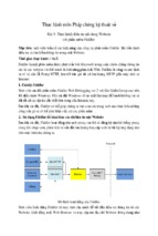
6.2.4 Principles of the Lab
1. Principles of Ethernet Communication
The company Xerox developed the Ethernet protocol based on the Carrier Sense Multiple Access / Collision
Detection (CSMA/CD) mechanism. The communication medium is a coaxial cable. The data transfer rate could
be 10Mb/s. If using twisted pair wires, the data transfer rate could be 100Mb/s. Currently the Ethernet follows
the IEEE802.3 standard.
1) Architecture
The architecture of an Ethernet based system is shown in Figure 6-10.
242
Embedded Systems Development and Labs; The English Edition
Ethernet Li
Figure 6-10. Ethernet architecture, schematic drawing.
2) Types
● Ethernet/IEEE802.3:
● 100M Ethernet:
● 1000M Ethernet:
using coaxial cable; the data transfer rate could be 10Mb/s.
uses twisted pair wire; data transfer rate could be 100Mb/s.
using optical cable or twisted pair wire.
3) Work Principles
The transportation method in Ethernet is Media Access Control technology that is also called Carrier Sense
Multiple Access / Collision Detection (CSMA/CD). The following are the descriptions of this technology:
● Carrier Sense: When your computer is trying to send information to another computer on the networks,
your computer should first monitor if there are information currently transferring on the network or if the
channel id idle.
● Channel Busy: If the channel is busy, then wait until the network channel is idle.
● Channel Idle: If the channel is idle, then transmit the message. Because the whole network is being shared
the same communication bus, all the network station can receive your message, but only the network station
you selected can receive your message.
● Collision Detection: When a network station is transmitting message, it needs to monitor the network
channels, detects if other network station are transmitting messages on the network. If yes, the messages
sent from two stations will be in collision that cause the message be damaged.
● Busy Stop: If there is network collision on the network, the transmission should stop immediately and a
“collision” signal should be sent to the network to let other stations know the collision has happen.
● Multiple Access: If the network station encountered collisions and stop transmission, it should wait for a
while and return to the first step, start the carrier sensing and transmission, until the data is successfully
transmitted.
All the network stations are transmitting messages through the above 6 steps.
Because at the same time, there is only one network station transmitting messages and other stations can only
receive or wait, the collision chances are increase when more network station added to the network. The
network stations will alternately follow the process monitorÆtransmitÆstop transmitÆwaitÆretransmit…
4) Ethernet/IEEE 802.3 Frame
The frame structure of the Ethernet/IEEE 802.3 protocol is shown in the following figure.
243
Embedded Systems Development and Labs; The English Edition
Figure 6-11 Ethernet/802.3 Frame Architecture
●
●
●
●
●
●
Preamble consists of alternative 0 and 1 that informs network stations to get ready. The IEEE802.3
preamble is 7 bytes followed by one byte of SOF. The Preamble includes the SOF, so its total length is 8
bytes.
Start of Frame (SOF) is one byte ended with two consequent 1. This byte stands for the start of the frame.
Destination and Source Addresses means the addresses of the sending workstation and receiving
workstation. The destination address is a single address or a broadcast address.
Data (Ethernet) will be transferred to higher protocols after the data has been processed in the physical
layer and the logic link layer. The minimum length of data is 46 bytes.
Data (802.3) will be filled to 64 bytes if the length of data is not more than 64 bytes.
Frame Check Sequence (FCS) consists of a 4-byte CRC that is generated by the sending device. The
receiving device will recalculate the CRC and compare is with the received CRC in order to make sure that
data has been transferred correctly.
5) Ethernet Driver Development Methods
Developing Ethernet drivers involves initializing and programming the RTL8019AS Ethernet interface chip and
providing data input/output and control interface to higher-level protocols. The RTL8019 chip is an Ethernet
controller made by the Realtek company of Taiwan. Because of its high performance and low price, it is widely
used in commercial products.
The main features of the RTL8019AS are:
● Meets Ethernet II and 802.3 (10 Base, 10 Base2 and 10 BaseT) standards.
● Full duplex and maximum 10 Mb/s in sending and receiving.
● Supports 8/16 bits data bus, 8-interrupt line and 16 base I/O addresses.
● Supports ITP, AUI and BNC automatic detection, Supports auto polarity correction for 10BaseT.
● Support 4 diagnostic LED pins with programmable outputs
244
Embedded Systems Development and Labs; The English Edition
●
100 pins PQFQ package.
RTL8019 consists of the following interfaces: remote DMA, local DMA, MAC (media access control) logic,
data CODEC, and others.
The remote DMA interface is an ISA bus that the processor write/read data to/from the RAM inside the
RTL8019. Microprocessor deals with remote DMA interface only. The local DMA interface is an
interconnection channel between RTL8019AS and network cable.
Bellow the MAC (media access control) logic completes the function:
•
when the processor transmits data to the network, the processor transmits first a frame of data to the
transmit buffer via the remote DMA channel;
•
then the processor sends a transmit command; when the RTL8019AS finishes the current frame
transmission, it starts to transmit the next frame;
•
the RTL8019As receives the data the MAC comparison. After the CRC verification, the data is
transferred to buffer via FIFO;
•
when the frame is full, the RTL8019As will inform the microprocessor through the interrupt or the
register flag bit.
FIFO receive/send 16 bytes data is used as a tampon buffer to reduce the DMA request frequency. The RTL8019
has two internal RAM blocks. One is 16Kb and occupies the address space 0x4000-0x7FFF. The other is 32Kb
and occupies the address space 0x0000-0x001F. The RAM is divided into pages of 256 bytes. Generally the first
12 pages (0x4000-0x4BFF) are used as the transmission buffer. The following 52 pages (0x4C00-0x7FFF) are
used as the receiver buffer. The page 0 is only 32 bytes (0x0000-0x001F) and is the PROM page. The PROM
page is used for storing the Ethernet physical address. In order to read/write data packages, the DMA mode is
needed to read/write the data to the 16 Kb RAM in the RTL8019AS. The RTL8019 has 32-bit input/output
addresses. The address offset is 0x00-0x1F where x00-0x0F are 16 register addresses. These registers hold the
pages addresses. They are PAGE0, PAGE1, PAGE2 and PAGE3. The bit PS1 and bit PS2 of CR (Command
Register) determines which page will be visited. But only the first 3 pages are compatible with NE2000. Page 3
is RTL8019 self defined page and is not compatible with other NE2000 chips (such as DM9008). The remote
DMA address is 0x10-0x17 and is used as remote DMA port. The reset port is 0x18-0x1F (8 addresses) that is
used to reset RTL8019AS. The application diagram of ATL8019As is shown in Figure 6-12.
245
Embedded Systems Development and Labs; The English Edition
Figure 6-12. RTL8019A C application schematic diagram.
Ethernet.c is the driver program of the RTL8019AS chip. The following describes briefly its functions:
● NicInit() 8019 initialization. The initialization steps are: (1) configure the chip to the jumper mode,
half-duplex. (2) Configure the receive/send buffer. Two buffers are used for sending data. Each buffer
occupies 6 pages (256 bytes) of internal RAM and it can transmit a maximum of 1536 bytes of Ethernet
data package. Another buffer is used for receiving data and consists of 20 pages (256 bytes/page) of internal
RAM block. (3) Set MAC address and broadcast address. MAC address is determined by mac_addr array.
(4) Configure the chip only receive the data package that match to the local MAC address (also can be
configured as receiving all packages or broadcast packages). Enable received interrupt. Enable CRC. (5)
Start the chip for receiving/sending data.
● NicClose() Close 8019AS data receive/send functions.
● NicReset() Reset 8019AS chip.
● NicOutput() Data package output. Fill the data package with a header of Ethernet data package. Set the
target MAC address according to the parameter. Write the content of Ethernet package to the send buffer.
Start DMA send function. This chip will automatically finish the sending.
● EtherInput() Data package input. Check the data receive flag register. If there is data in the buffer, then
receive the header of the package from the receive buffer. If the content of the header is correct, then
according to the data length in the header, read the content of data from the package and transfer it to the
higher layer interface. Make the pointer to the current receive buffer to the last page of the buffer.
2. IP Network Protocols
TCP/IP protocol is a group of protocols including TCP (Transmission Control Protocol) and IP (Internet
Protocol), UDP (User Datagram Protocol), ICMP (Internet Control Message Protocol) etc.
TCP/IP was first time introduced in 1973 by two researchers at Stanford University. At that time the US ARPA
(Advanced Research Project Agency) planed to implement interconnections between different networks. ARPA
aided the research and development of inter-network connections. In 1977-1979, the TCP/IP architecture and
standard was developed and is almost the same as the current TCP/IP architecture. Around 1980s, the US
DARPA started to port all the machines to the TCP/IP network. From 1985, NSF (National Scientific
246
Embedded Systems Development and Labs; The English Edition
Foundation) started to support TCP/IP research and gradually played an important role. NFS aided the
establishment of the global Internet network. and used TCP/IP as its communication protocol.
1) Architecture
TCP/IP is a four layers protocol. Every layer is independent and has its own specific function. The TCP/IP layer
structure is shown in Figure 6-13.
Application Layer Layer 4
Transmission Layer Layer 3
Internet Layer Layer 2
Network Interface Layer Layer 1
●
●
●
●
Figure 6-13 TCP/IP Layered Protocol
Network Interface Layer: Responsible for receiving and sending physical frames. This layer defines the
rules of forming frames and the rules of transmission. Frame represents a series of data and a frame is a
communication unit of the network transmission. The network layer puts frames to the network or receives
frames from the networks.
Internet Layer: Responsible for the inter-communication between two network nodes. This layer defines the
format of the “information package” in the Ethernet and the information transmission mechanisms from one
network node to the destination via one or more routers and routing algorithms. The main protocols used in
this layer include IP, ARP, ICMP and IGMP.
Transmission Layer: Responsible for communication of end-to-end. It creates, manages and deletes
end-to-end connections for two-user processes. The main protocols used in this layer include TCP, UDP,
etc.
Application Layer: It defines the application programs that use the Internet. Application programs access
the network via this layer by following BSD network application interface standard. The main protocols
include SMTP, FTP, TELNET, and HTTP, etc.
2) An Introduction to the Main Protocols
(1) IP Protocol
Internet Protocol (IP) is the heart of TCP/IP and the most important protocol in the network layer.
IP layer receives data packages from the lower layer (network interface layer, Ethernet device driver for
example) and sends these data packages to the higher layer – TCP or UDP layer. IP layer can also receive data
from TCP or UDP layer and sends this data to the lower layer. The IP data package is not reliable because IP
does not support mechanisms to check the data integrity and the transmission order of the packages. The IP data
package has its sender’s IP address (source address) and its receiver’s IP address (target address).
IP protocol is a non-connection protocol and is mainly responsible for addressing between the hosts and setting
the route for data packages. Before the data is exchanged, it doesn’t establish sessions because it doesn’t
guarantees error free data transfers. On the other hand, when data is being received, IP doesn’t need to receive
acknowledgment information. As a result the IP protocol is not a reliable protocol. If the IP address is for the
current host, the IP will send the data directly to this host. If the IP address is for a remote host, the IP will check
247
Embedded Systems Development and Labs; The English Edition
the route of the remote host from the route table in the local host (like we dial 114). If a route is found, the IP
will use this route to transfer data; if no route is found, the data package will be sent to a default gateway of the
source host (this gate way is also called a router).
The current IP protocol includes the IPv4 version and the v6 version. IPv4 is currently being widely used; IPv6
is the basic protocol that will be used in the next generation of high speed Internet.
The header of IP protocol is shown in Figure 6-14.
0
4
8
16
32
----------------------------------------------------------------------|Version
|Header Length |Service Type| Total Length
|
---------------------------------------------------------------------|
Identification
|Flags|Fragment Offset|
----------------------------------------------------------------------|
Time to Live
| Protocol
| Header Checksum
|
----------------------------------------------------------------------|
Source IP Address
|
----------------------------------------------------------------------|
Destination IP Address
|
----------------------------------------------------------------------|
Options
|
==================================== ===
|
Data
|
----------------------------------------------------------------------Figure 6-14 IPv4 Data Package Format
The C structure of the IP header is defined as following:
struct ip_header
{
UINT
ip_v:4;
/* Version
UINT
ip_hl:4;
/* Header Length */
UINT8
ip_tos;
UINT16 ip_len;
*/
/* Service Type
*/
/* Total Length */
248
Embedded Systems Development and Labs; The English Edition
UINT16 ip_id;
/* Identification
*/
UINT16 ip_off;
/* Fragment Offset */
UINT8
ip_ttl;
/* Time to Live */
UINT8
ip_p;
/* Higher layer Protocol */
UINT16 ip_sum;
/* checksum */
struct in_addr ip_src, ip_dst;
/* Source and Destination IP Address */
};
The description of these parameters are as following:
ip_v Ip protocol version, Ipv is 4, Ipv6 is 6
ip_hl IP Header length. Based on 4 bytes unit. The length of IP header is fixed as 20
bytes. If there are no options included, this value is 5.
ip_tos Service type, describes the priority of services.
ip_len IP package length. Use byte as a unit.
ip_id Identification of this package
ip_off Fragment Offset. Used with the above IP for reunite fragments.
ip_ttl Time to live. Minus 1 when passing a route, throw away the data package until
this value becomes 0.
ip_p Protocol. The higher layer protocols that create this package. TCP or UDP,for
example.
ip_sum Header checksum. It is used to provide verification to the IP header.
ip_src,ip_dst Sender and receiver IP address.
For more detailed information of IP protocol, please refer to RFC791.
The IP address is actually a method used to unite the network physical addresses with the higher layer software
via Internet Layer. This method uses uniform address format via a uniform management. Different hosts within
the Ethernet have different addresses. In IPv4, each host IP address is 32 bits that consists of 4 bytes. In order to
conveniently read the address by the users, decimal with dot separation format is used. For example,
211.154.134.93 is the IP address of Embedded Development Network Website. Each IP address has two parts.
The network section describes the type of different scale networks. The host section describes the address of the
249
Embedded Systems Development and Labs; The English Edition
host in the network. According to the size of the network scale, the IP address can be divided into five classes A,
B C, D, E and F. Among these classes, A, B and C are used as the main address types. D class address is used as
multi transmission address for multicasting. E class address is used as an extended optional address.
(2) TCP Protocol
If an IP package has a packaged TCP package, the IP layer will transmit this package to the higher TCP layer.
The TCP will sort the packages and do error checking. A virtual circuit connection will also be established. TCP
package has a series number and an acknowledgment. The received package will be sorted by the series number.
The damaged package will be re-transmitted.
The TCP sends its package to the higher layer programs such as Telnet service program or client programs.
Application programs will alternatively send the message back to the TCP layer. The TCP layer will send the
message down to the lower IP layer, device driver and physical media and at last to the end receiver. The format
of the TCP protocol data package header is shown in Figure 6-15.
0
4
8
10
16
24
32
----------------------------------------------------------|
Source Port
| Destination Port
|
----------------------------------------------------------|
Series number
|
----------------------------------------------------------|
Acknowledgment Number
|
----------------------------------------------------------|
|
|U|A|P|S|F|
|
| HL | Reserved |R|C|S|Y|I| Window
|
|
|
|G|K|H|N|N|
|
----------------------------------------------------------|
Checksum
| Emergency Pointer
|
----------------------------------------------------------|
Options
| Fills
|
----------------------------------------------------------Figure 6-15 TCP Protocol Data Package Header Format
For detail information about the TCP protocol, please refer to the related documentations. A TCP session is
established by a three times handshake initialization. The purpose of three times handshake initialization is to
synchronize the data transmission, inform other hosts about the data quantity it can be received at one time and
establish the virtual connection. The simplified process of three times handshake initialization is as following:
(1) Initialize the host and send a session request.
(2) The receiver host replies by sending a data segment with the following items: synchronization flag, the
250
Embedded Systems Development and Labs; The English Edition
series number of the data that will be sent, acknowledgment with the next series number of next data segment
that will be received.
(3) Request the host to send another data segment with acknowledges series number and acknowledge number.
(3) UDP Protocol
UDP is at the same layer as the TCP protocol. UDP do not perform data package series, error
checking or retransmission. As a result, UDP is not used to virtual circuit services or connection
oriented services. UDP is mainly used by those polling-answer services, NFS for example. These
services require less information exchanging than FTP or Telnet. UDP services include NTP (Network
Time Protocol) and DNS (DNS also use TCP). The header of UDP package is shown at Figure 6-16.
0
16
32
--------------------------------------------------------------|
UDP Source Port
| UDP Target Port
|
--------------------------------------------------------------| UDP Datagram Length
| UDP Datagram Checksum |
--------------------------------------------------------------Figure 6-16 UDP Protocol Data Package Header Format
For more detailed information, please refer to related RFC documentation.
UDP protocol is often used in software applications that don’t need acknowledgment and that transmit small
amounts of data.
(4) ICMP Protocol
ICMP is at the same layer as the IP protocol and is used to transmit the IP control message. It is mainly used to
provide route information of the target address. The Redirect message of ICMP provides more accurate route
information for the host that connects to other systems. The Unreachable message means routing problems. If a
route cannot be used, ICMP can decently terminate a TCP connection. PING is the most often used, ICMP based
service.
For more detailed information about ICMP, please refer to the related RFC documentation.
(5) ARP Protocol
In order to communicate between networks, a host must know the hardware address (network card physical
address) of the target host. Address resolution is a process that maps the host IP address to the hardware address.
Address Resolution Protocol (ARP) is used to get the hardware addresses in the same network.
The local network resolution process is as following:
1. When a host needs to communicate with another host, it initializes an ARP request. If the IP protocol
has identified its local IP address, the source host will check out the hardware address of the target host
from the ARP buffer.
2. If the target address of the target host mapping cannot be found, the ARP protocol will broadcast the
source host IP address and hardware address. All hosts in the network will receive this request via
251
Embedded Systems Development and Labs; The English Edition
multicasting and process the request.
3. Every host in the network receives the muticast request and searches for the corresponding IP address.
4. When the target host finds that the IP address broadcasted is the same as its own IP address, the target
host will send an ARP reply to inform its hardware address to the source host. The target host also
updates its ARP buffer with the source host IP address and hardware address. The source host will
establish a communication after receives the reply.
For more detailed information about ARP, please refer to related RFC documentation.
(6) TFTP Protocol
TFTP is a simple protocol for transferring files. It is based on the UDP protocol. It supports user receive/send
files from/to a remote host computer. This protocol is suitable only for small files. It doesn’t have same
functions as the FTP protocol. It can only receive or write files from/to the host server computer. It can’t list file
directory, no verification, it only transfers 8 bit type data.
Because TFTP uses UDP and UDP uses IP, and IP can communicate using other methods, a TFTP data package
includes the following segments: local header, IP header, data package header, TFTP header, and the TFTP data.
The TFTP doesn’t specify any data in the IP header but it uses UDP source and target address and length. The
TID used in TFTP is a port number that must be within 0-65535 range.
The initial connection needs to send WRQ (Write Remote Request) or RRQ (Read Remote Request) and receive
an acknowledgment message, a definite data package or the first data block. Normally an acknowledgment
package includes a package number. Every data package has its block number. The block number start from 0
and the numbers are continuous. The WRQ is a special package and its block number is 0. If the receiver
receives a wrong package, the received package will be rejected. When a connection is created, the two
communicating parts will randomly select a TID. Because the selection is random, the chance of the same TID
is very small. Each package has two IDs, one is for the sender, and the other is for the receiver. In the first
request, the package will be sent to port 69 of the receiver host. When the receiver host sends an
acknowledgment, it will use a selected TID as the source TID and use the TID in the former package as its target
TID. These two IDs will be used in the entire process of communication.
After the connection is created, the first data package with series number 1 will be sent from the host. Later on,
the two hosts must guarantee to communicate with the specified TIDs. If the source ID is not the same as the
specified ID, the data package will be thrown away as a message that is being sent to a wrong address.
For more detailed information about TFTP, please refer to related RFC documentation.
3) Development Methods of Network Application Programs
There are two methods of developing network application programs. One is by using the BSD Socket standard
interface. Using this method, the programs can be ported to other systems. The other method is by using directly
the transmission layer interface. This method is more efficient.
(1) BSD Socket Interface Programming Methods
Socket is a programming method of communicating to other programs via standard FD. Each socket uses a half
related description {protocol, local address, local port}. A completed socket uses a completed description
{protocol, local address, local port, remote address, remote port}. Each socket has a local number that is
specified by the operating system.
Socket has three types:
252
Embedded Systems Development and Labs; The English Edition
●
Stream Socket (SOCK_STREAM). The stream socket provides a reliable stream oriented communication
connection. It uses the TCP protocol and guarantees the correct data transmission and series number
checking.
● Datagram Socket (SOCK_DGRAM). The Datagram Socket defines a non-connection service. Data is
transferred independently and the order is not relevant. It doesn’t guarantee that the data transmission is
reliable and correct. It uses the UDP protocol.
● Original Socket. The original socket allows the user to directly use the lower level protocol (IP or ICMP for
example). The original socket is powerful but not convenient to use. It is mostly used in developing other
protocols.
The Socket programming flow diagram is shown at Figure 6-17.
Server End
Create a server-end socket
Server end socket binds to a
port
Client End
Listen to the connection
requests from clients
Create a client-end socket
Program blocks until the client
send a connection request
Send a connection request via
the server IP address and the
server port number
Receive data from clients
Send data to server
Process the data
Send the data to clients
Receive data
Figure 6-17 Socket Programming Flow Diagram
The most commonly used Socket interface functions are the following:
socket() -- Create a socket
bind() -- specify a local address
253
- Xem thêm -