VIETNAM NATIONAL UNIVERSITY HANOI
UNIVERSITY OF ENGINEERING AND TECHNOLOGY
Phạm Văn Thành
DEVELOPMENT OF A REAL-TIME SUPPORTED
SYSTEM FOR FIREFIGHTERS ON-DUTY
MASTER’S THESIS IN ELECTRONICS AND COMMUNICATIONS
ENGINEERING
Hanoi - 2016
VIETNAM NATIONAL UNIVERSITY HANOI
UNIVERSITY OF ENGINEERING AND TECHNOLOGY
Phạm Văn Thành
DEVELOPMENT OF A REAL-TIME SUPPORTED
SYSTEM FOR FIREFIGHTERS ON-DUTY
Field: Electronics and Communications Engineering
Major: Electronic Engineering
Code: 60520203
MASTER’S THESIS IN ELECTRONICS AND COMMUNICATIONS
ENGINEERING
SUPERVISOR: Assoc. Prof. Dr. Trần Đức Tân
Hanoi - 2016
AUTHORSHIP
I hereby declare that the work contained in this thesis is of my own and
has not been previously submitted for a degree or diploma at this or any other
higher education institution. To the best of my knowledge and belief, the thesis
contains no materials previously published or written by another person except
where due reference or acknowledgement is made.
Author
Student
Phạm Văn Thành
i
ACKNOWLEDGEMENT
I would like to express my sincere thanks to my advisor Assoc. Prof.
Tran Duc-Tan, the professional of Faculty of Electronics and
Telecommunication, University of Engineering and Technology – Vietnam
National University, Hanoi for the guidance and support given to me
throughout the thesis.
Special thanks to the lecturers of Faculty of Electronic and
Communication for their help and guidance me in all thesis process.
Thanks for all members of the MEMS Lab for their help and discussed
conversations.
At the end, I would like to thank my parents, my relatives and my
friends because their comfort and supporting are the power for me going to
success.
Sincerely
Pham Van Thanh
ii
TABLE OF CONTENTS
AUTHORSHIP ........................................................................................................ i
ACKNOWLEDGEMENT ..................................................................................... ii
Abstract ................................................................................................................... v
List of Figures ........................................................................................................ vi
List of Tables .......................................................................................................... ix
List of Abbreviations .............................................................................................. x
INTRODUCTION .................................................................................................. 1
1.1. Overview about Firefighters .......................................................................... 1
1.2. The research objectives .................................................................................. 2
1.3. The role of fall detection system .................................................................... 3
1.4. The available supporting systems for Firefighters ......................................... 3
BACKGROUND AND HARDWARE DESIGN ................................................. 5
2.1. Hardware ........................................................................................................ 5
2.1.1. MCU PIC18f 4520 ................................................................................... 5
2.1.2. ADXL345 accelerometers sensor ............................................................ 7
2.1.3. SIM900 ................................................................................................... 10
2.1.4. MQ7 CO sensor ..................................................................................... 11
2.2. Solfware ....................................................................................................... 13
2.2.1. I2C Interface ........................................................................................... 13
2.2.1.1. Masters and Slaves .......................................................................... 14
2.2.1.2. The I2C Physical Protocol ............................................................... 14
2.2.1.3. Clock ................................................................................................ 15
2.2.1.4. I2C Device Addressing ..................................................................... 15
2.2.1.5. The I2C Software Protocol .............................................................. 16
2.2.1.6. Reading from the Slave .................................................................... 16
iii
2.2.2. UART communication ............................................................................ 17
2.2.2.1. The Asynchronous Receiving and Transmitting Protocol ............... 17
2.2.3. Timer ...................................................................................................... 18
2.2.3.1. Timer0 features [30]: ...................................................................... 18
2.2.3.2. Timer1 features [30]: ...................................................................... 18
2.2.3.3. Timer2 features [30]: ...................................................................... 19
2.2.3.4. Timer3 features [30]: ...................................................................... 19
2.3. The integrated system .................................................................................. 19
2.3.1. Power module ........................................................................................ 20
2.3.2. MCU module .......................................................................................... 20
2.3.3. SIM900 module ...................................................................................... 20
2.3.4. Sensor ADXL345.................................................................................... 20
2.3.5. Sensor MQ7 ........................................................................................... 21
METHODS ............................................................................................................ 22
3.1. The 3-DOF accelerometer ............................................................................ 22
3.2. Model of fall data processing ....................................................................... 23
3.3. The fall detection algorithms ....................................................................... 24
3.4. Posture Recognition Module ........................................................................ 25
3.5. Cascade Posture Recognition ....................................................................... 27
3.6. Fall Detection Module ................................................................................. 28
3.7. CO Detection Module .................................................................................. 29
3.8. Final Decision .............................................................................................. 31
RESULTS AND DISCUSSIONS ........................................................................ 34
4.1. Experimental setup and testing .................................................................... 34
4.2. The evaluation with other public datasets .................................................... 41
CONCLUSIONS ................................................................................................... 45
LIST OF AUTHOR’S PUBLICATIONS ........................................................... 46
References ............................................................................................................. 47
iv
Abstract
The firefighters can be injured by unintentional falls during the
implementation tasks because of the broken in floors, structure elements; gas
bombs; liquid boil ejection and toxic gases… in a fire. Therefore, this thesis
aims to develop a portable and efficient device to monitor the falls by
integrating a micro controller, a 3-DOF (Degrees of Freedom) accelerometer
sensor, a MQ7 sensor (Semiconductor Sensor for Carbon Monoxide), a
GSM/GPRS (Group Special Mobile/General packet radio service) modem, and
the corresponding embedded fall detection algorithms. By developing
algorithms and the corresponding simulations to monitor the fall event which
can distinguish between being fall and the other daily activities (ADLs) such as
standing, walking, running, sitting, lying. The signals from accelerometer are
sent to the micro controller to monitor and alert the fall events. The cascade
posture recognition is proposed to enhance the fall detection accuracy by
determining if the posture is a result of a fall. Furthermore, MQ7 sensor is
integrated into the proposed system to confirm the fall directly in emergency
situations when air supporting device is working in failure. Based on the
detection results, if a person falls with faint, an alert message will be sent to
their leader via the GSM/GPRS modem. We had carefully investigated the
threshold values (to determine the fall events) and the window size(to
determine the time frame for analyzing) by MATLAB. After that, we selected
the most suitable values for these parameters to achieve the optimal
performance when it is working in emergency places.
Keywords: Firefighters, Acceleration, Fall detection, Posture recognitions, CO
detection, Threshold investigations.
v
List of Figures
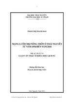
Figure 1-1– US Firefighter injuries by type of duty during 2014 [1] ................. 1
Figure 1-2– Firefighter injury on-duty [5] .......................................................... 2
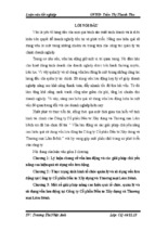
Figure 1-3– Personal alert safety system (PASS) devices from various
manufacturers [6]................................................................................................. 4
Figure 2-1– PIC18f 4520 pins [30] ..................................................................... 6
Figure 2-2– The structure of PIC18f 4520 [30] .................................................. 7
Figure 2-3– ADXL345 Digital Accelerometer ................................................... 8
Figure 2-4– The functional block diagram of ADXL345 [31]............................ 9
Figure 2-5– The axis of ADXL345 Accelerometer [31] ..................................... 9
Figure 2-6– The positions and output responses [31] ....................................... 10
Figure 2-7– The SIM900 Module [34] .............................................................. 10
Figure 2-8– The CO sensor [36]........................................................................ 12
Figure 2-9– I2C connection diagram [37].......................................................... 13
Figure 2-10– The physical I2C bus [32] ............................................................ 13
Figure 2-11– Start and stop sequences [32] ...................................................... 14
Figure 2-12– Communication between two devices [33] ................................. 17
Figure 2-13– Basic UART packet form: 1 start bit, 8 data bits, 1 parity and 1
stop bit [33]........................................................................................................ 18
Figure 2-14– The connected modules in the proposed system ......................... 19
Figure 3-1– Position of the 3-DOF accelerometer in waist body ..................... 23
Figure 3-2– Fall data processing for fall detection system ............................... 24
Figure 3-3– The summary of fall detection system ........................................... 24
vi
Figure 3-4– The proposed algorithms of fall detection ..................................... 25
Figure 3-5– Flow chart of posture recognition .................................................. 26
Figure 3-6– Illustration of two threshold th1 and th2 [39] ................................. 26
Figure 3-7– Ay acceleration vs. posture cognitions [39] ................................... 27
Figure 3-8– Fall detection module .................................................................... 28
Figure 3-9– L2 acceleration pattern of a fall sample [9].................................... 29
Figure 3-10– CO detection algorithm ............................................................... 29
Figure 3-11– CO sensor location....................................................................... 31
Figure 3-12– Fall decision using fall detection combined cascade posture
recognitions and CO alert level ......................................................................... 32
Figure 4-1– The author testing and measuring the CO level in the fire ............ 34
Figure 4-2– The CO level in the fire ................................................................. 35
Figure 4-3– CO levels between clean and smoke environments ...................... 35
Figure 4-4– Standing ......................................................................................... 36
Figure 4-5– Standing posture ............................................................................ 36
Figure 4-6– Walking.......................................................................................... 37
Figure 4-7– Walking posture ............................................................................. 37
Figure 4-8– Standing and sitting ....................................................................... 37
Figure 4-9– Recognition detection of standing and sitting ............................... 38
Figure 4-10– Fall detection with the window size of 10 samples and threshold
th4 = 1.4 m/s2 .................................................................................................... 39
Figure 4-11– Fall detection with the window size of 20 samples and threshold
th4 = 1.4 m/s2 .................................................................................................... 39
Figure 4-12– Fall detection with the window size of 30 samples and threshold
th4 = 1.4 m/s2 .................................................................................................... 39
vii
Figure 4-13– Fall decision without cascade posture recognitions [39] ............. 40
Figure 4-14– Fall decision with cascade posture recognitions [39] .................. 40
viii
List of Tables
Table 1: The Pic18f4520 features [30] ................................................................ 6
Table 2: The technical data of MQ7 [35] .......................................................... 12
Table 3: Assigned Values for Different Postures [38] ...................................... 27
Table 4: Carbon Monoxide Concentrations, COHb Levels, and Associated
Symptoms [11] .................................................................................................. 30
Table 5: Final Decision of Fall using Cascade Posture Cognition. ................... 33
Table 6: Features of the public and our recorded fall detection datasets .......... 41
Table 7: The result of applying our algorithms to detect the fall events on other
exiting datasets .................................................................................................. 44
ix
List of Abbreviations
ADLs
Daily activities
CCS
Cascading Style
CO
Carbonmonioxide
DOF
Degree Of Freedom
GPRS
General Packet Radio Service
I2 C
Inter – Integrated Circuit
LCD
Liquid Crystal Display
MCU
Microcontroller Unit
PASS
Personal Alert Safety System
SMS
Short Message Service
SPI
Serial Peripheral Interface
UART Universal Asynchronous Receiver/Transmitter
UFFP
University of Firefighting and Prevention
ZCR
Zero Cross Rate
x
Chapter 1
INTRODUCTION
1.1. Overview about Firefighters
According to [1] there are 63,350 US firefighter injuries in 2014 with
27,015 occurred in fireground operations and a total of 64 firefighters died onduty at the same year [4].
US Firefighter injuries by type of duty
during 2014
Non-Fire emergency
6%
17%
Fire ground (fall, slip, jump
(28.7%) and overexertion, strain
(25.0%))
Training
23%
11%
43%
Other duty
Responding or returning from an
incident
Figure 1-1– US Firefighter injuries by type of duty during 2014 [1]
1
In Vietnam, there are thousand of fires burning every year such as: 2357
and 2792 in 2014 and 2015 respectively [2] [3]. This is an alarm signal to alert
about unsafely for firefighters in both US, Vietnam and in worldwide because
they always are working and facing with a lot of dangers while they still have
not enough and suitable supporting systems to protect their lives such as the
fall detection systems in order to help them to escape from the dangerous
situations.
Figure 1-2– Firefighter injury on-duty [5]
1.2. The research objectives
Based on the actual problem, this thesis mainly focus on improving the
fall detection algorithms to distinguish between being fall and other activities
of firefighters on-duty combined with CO level measurement to prevent the
death because of the broken in floors, structure elements; gas bombs; liquid
boil ejection and toxic gases and broken in air supporting devices...
2
1.3. The role of fall detection system
Fall detection system plays very essential role to support Firefighters onduty to avoid the death because of the heat, smoke as others dangerous
problems which can be appreared in a fire as discussed above or any other
situations. When facing with the death if they donot have enough and siutable
supporting systems, it will effect directly to their lives. Hence, the thesis
mainly focus on proposed a system that can detect the fall events and CO
threshold level as well as, and send out the message content to their leader and
relative member for the help.
The proposed system can distinguish between being fall and others daily
as on-duty activities of firefighters as running, walking, sitting, jumping,... in
actual recorded data. Furthermore, most of firefighters and pedestrians were
died by toxic smokes, CO is one of the most dangerous gas with the name
“silent killer” and the process to find out the danger CO value in a fire is
extremly important to protect the health, lives of firefighters.
1.4. The available supporting systems for Firefighters
There are several published methods used to detect the fall events in
recent year such as: image processing [7], location sensors [8], smart phones
and accelerometers [9][10]…but the reported publications were only used for
the elderly and patients in clean air environments with long time to confirm
self-stand up ability. Therefore, it is not suitable for firefighter’s activities in
the fire environment conditions.
The department of Homeland Security also was developed a Personal
alert safety system (PASS) [6] devices to equip for firefighters to detect high
heat and smoke of a fire. PASS devices are designed to signal for aid via an
audible alarm signal if a fire fighter becomes incapacitated on the fire ground.
Furthermore, it can sense movement or lack of movement and activate a 95
decibel alarm if lack of motion exceeds a specific time period. Nevertheless, in
a real fire situation, there are variety of noise like people voice; the operation of
fire protection systems, fire truck, fire pumpes...Therefore, audible alarm signal
is not useful in a big fire burning.
3
Figure 1-3– Personal alert safety system (PASS) devices from various
manufacturers [6]
Based on the above limitations, this paper proposed to develop a realtime, low cost and high accuracy system which uses a 3-DOF accelerometer,
MQ7 CO sensor combined with development the algorithms and the
corresponding simulation process to monitor the fall events, which can be
distinguished between fall and ADLs. It’s good for the fire environment and
firefighters activities. Furthermore, we have used MATLAB to simulate and
chosen the best size of the window and values of the threshold to improve the
accuracy and performance of the system. The system can work well both in
clean and fire environments with the first scenario that combined fall detection
and posture recognitions and re-checked after 3 seconds to confirm they are
faint or not. The second scenario is the output of both fall detection and CO
detection modules to confirm they were fell or not, which caused by having air
supporting devices broken.
4
Chapter 2
BACKGROUND AND HARDWARE
DESIGN
2.1. Hardware
2.1.1. MCU PIC18f 4520
5
Figure 2-1– PIC18f 4520 pins [30]
Pic 18f4520 is a 10-Bit A/D and nanoWatt Technology microcontroller
was developed by Microchip with some features as bellow:
Table 1: The Pic18f4520 features [30]
Features
Operating Frequency
Program Memory (Bytes)
Program Memory (Instructions)
Data Memory (Bytes)
Data EEPROM Memory (Bytes)
Interrupt Sources
I/O Ports
Timers
Capture/Compare/PWM Modules
Enhanced
Capture/Compare/PWM Modules
Serial Communications
Parallel Communications (PSP)
10-Bit Analog-to-Digital Module
Resets (and Delays)
PIC18F4520
DC – 40 MHz
32768
16384
1536
256
20
Ports A, B, C, D, E
4
1
1
MSSP, Enhanced USART
Yes
13 Input Channels
POR, BOR, RESETInstruction, Stack Full,
Stack Underflow (PWRT, OST),
MCLR(optional), WDT
Programmable High/Low-Voltage
Yes
Detect
Programmable Brown-out Reset
Yes
Instruction Set
75 Instructions; 83 with Extended
Instruction Set Enabled
Packages
40-Pin PDIP, 44-Pin QFN,44-Pin TQFP
6
Figure 2-2– The structure of PIC18f 4520 [30]
2.1.2. ADXL345 accelerometers sensor
The ADXL345 is a small, thin, low power, 3-axis accelerometer
with highresolution (13-bit) measurement at up to ±16 g [31]. Digital output
7
data is formatted as 16-bit twos complement and is accessible through either a
SPI (3- or 4-wire) or I2C digital interface
Highlight features [31]:
- Ultralow power: as low as 40 μA in measurement mode and 0.1
μA in standby mode at VS= 2.5 V (typical)
- Power consumption scales automatically with bandwidth
- User-selectable resolution. Fixed 10-bit resolution. Full resolution,
where resolution increases with grange, up to 13-bit resolution at ±16 g
(maintaining 4 mg/LSB scale factor in all granges)
- Tap/double tap detection
- Activity/inactivity monitoring
- Free-fall detection
- Supply voltage range: 2.0 V to 3.6 V
- SPI (3- and 4-wire) and I2C digital interfaces
- Measurement ranges selectable via serial command
- Wide temperature range (−40°C to +85°C)
Figure 2-3– ADXL345 Digital Accelerometer
8
- Xem thêm -