Mô tả:
datasheet
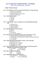
Transmissive Photosensors (Photo Interrupters)
CNA1015
Unit : mm
Photo Interrupters
14.0
Overview
(2.5)
0.5±0.1
(4-0.45)
Features
Gap width : 5 mm
2
3
1
4
2.2±0.15
,,,,
10.0 min.
2.5
A'
(10.0)
Position detection accuracy : 0.3 mm
(C1)
Device
center
10.0
CNA1015 series is a transmissive photosensor series in which a
high efficiency GaAs infrared light emitting diode is used as the
light emitting element, and a high sensitivity phototransistor is used
as the light detecting element. The two elements are arranged so as
to face each other, and objects passing between them are detected.
5.0
5.0±0.15
A
(4-0.45)
(2.54)
SEC. A-A'
The type directly attached to PCB
(Note)
1. Tolerance unless otherwise specified is ±0.3.
2. ( ) Dimension is reference.
Absolute Maximum Ratings (Ta = 25˚C)
Parameter
Symbol Ratings
Reverse voltage (DC)
Input (Light
Forward current (DC)
emitting diode)
Power dissipation
Collector current
VR
5
Unit
IF
50
mA
PD*1
75
mW
IC
20
mA
Output (Photo Collector to emitter voltage VCEO
transistor)
Emitter to collector voltage VECO
30
V
5
V
Collector power dissipation
PC*2
100
mW
Operating ambient temperature
Topr –25 to +85
˚C
Storage temperature
Tstg –40 to +100
˚C
Temperature
*1
*2
Internal connector
V
2
3
1
4
Pin connection
Input power derating ratio is 1.0 mW/˚C at Ta = 25˚C.
Output power derating ratio is 1.33 mW/˚C at Ta = 25˚C.
Electrical Characteristics (Ta = 25˚C)
Parameter
Symbol
Forward voltage (DC)
Input
characteristics Reverse current (DC)
Output characteristics Collector cutoff current
Conditions
VF
IF = 20mA
IR
VR = 3V
ICEO
VCE = 10V
Collector current
IC VCC = 5V, IF = 20mA, RL = 100Ω
Transfer
Collector
to
emitter
saturation
voltage
V
CE(sat) IF = 40mA, IC = 1mA
characteristics
Response time
tr , tf* VCC = 5V, IC = 1mA, RL = 100Ω
*
min
typ
max
Unit
1.25
1.4
V
10
µA
10
200
nA
10
mA
0.4
V
0.5
5
µs
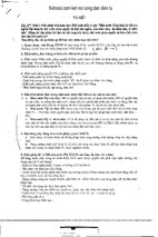
Switching time measurement circuit
Sig.IN
VCC
(Input pulse)
90%
10%
Sig.OUT (Output pulse)
RL
,,,,
,,
50Ω
tr
tf
tr : Rise time (Time required for the collector photo current to
increase from 10% to 90% of its final value)
tf : Fall time (Time required for the collector photo current to
decrease from 90% to 10% of its initial value)
1
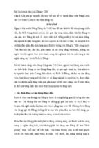
Transmissive Photosensors (Photo Interrupters)
IF , IC — Ta
IF — VF
VF — Ta
60
1.6
Ta = 25˚C
IF
30
IC
10
VF (V)
30
20
0
20
40
60
80
0
100
0
IC — IF
0.4
0.8
1.2
1.6
0.4
0
– 40 – 20
2.4
10 –1
10 –1
1
40
0
20
VCC
10 –1
60
80
Ambient temperature Ta (˚C )
100
Sig.
OUT
RL
tr
,
,,
Sig.
OUT
50Ω
10 –2
10 –1
1
td
90%
10%
IC (%)
1
Sig.IN
100
VCE = 5V
Ta = 25˚C
IF = 20mA
100Ω
10 –1
80
IC — d
tr (µs)
Rise time
1
60
100
RL = 1kΩ
500Ω
10
40
Ambient temperature Ta (˚C )
VCC = 5V
Ta = 25˚C
10 2
40
80
tr — IC
VCE = 10V
20
120
0
– 40 – 20
10 2
10
10 2
0
IC (%)
10mA
1
ICEO — Ta
10
100
VCE = 5V
IF = 20mA
Collector to emitter voltage VCE (V)
10 3
80
20mA
Forward current IF (mA)
10 –2
– 40 – 20
60
IC — Ta
IF = 30mA
10
10 –2
10 –1
10 2
10
40
160
Relative output current
IC (mA)
1
1
20
Ta = 25˚C
10
10 –2
10 –1
0
Ambient temperature Ta (˚C )
IC — VCE
Collector current
IC (mA)
2.0
10 2
VCE = 5V
Ta = 25˚C
Collector current
1mA
0.8
Forward voltage VF (V)
10 2
ICEO (nA)
10mA
10
Ambient temperature Ta (˚C )
2
1.2
80
Relative output current
0
– 25
40
Forward voltage
40
20
IF = 50mA
50
IF (mA)
50
Forward current
Forward current, collector current
IF , IC (mA)
60
Dark current
CNA1015
60
Criterion
0
d
40
20
tf
10
Collector current IC (mA)
102
0
0
1
2
3
4
Distance d (mm)
5
6
- Xem thêm -