HVAC
Administrator Guide
AVEVA Solutions Ltd
Disclaimer
Information of a technical nature, and particulars of the product and its use, is given by AVEVA
Solutions Ltd and its subsidiaries without warranty. AVEVA Solutions Ltd and its subsidiaries disclaim
any and all warranties and conditions, expressed or implied, to the fullest extent permitted by law.
Neither the author nor AVEVA Solutions Ltd, or any of its subsidiaries, shall be liable to any person or
entity for any actions, claims, loss or damage arising from the use or possession of any information,
particulars, or errors in this publication, or any incorrect use of the product, whatsoever.
Copyright
Copyright and all other intellectual property rights in this manual and the associated software, and every
part of it (including source code, object code, any data contained in it, the manual and any other
documentation supplied with it) belongs to AVEVA Solutions Ltd or its subsidiaries.
All other rights are reserved to AVEVA Solutions Ltd and its subsidiaries. The information contained in
this document is commercially sensitive, and shall not be copied, reproduced, stored in a retrieval
system, or transmitted without the prior written permission of AVEVA Solutions Ltd. Where such
permission is granted, it expressly requires that this Disclaimer and Copyright notice is prominently
displayed at the beginning of every copy that is made.
The manual and associated documentation may not be adapted, reproduced, or copied, in any material
or electronic form, without the prior written permission of AVEVA Solutions Ltd. The user may also not
reverse engineer, decompile, copy, or adapt the associated software. Neither the whole, nor part of the
product described in this publication may be incorporated into any third-party software, product,
machine, or system without the prior written permission of AVEVA Solutions Ltd, save as permitted by
law. Any such unauthorised action is strictly prohibited, and may give rise to civil liabilities and criminal
prosecution.
The AVEVA products described in this guide are to be installed and operated strictly in accordance with
the terms and conditions of the respective license agreements, and in accordance with the relevant
User Documentation. Unauthorised or unlicensed use of the product is strictly prohibited.
First published September 2007
© AVEVA Solutions Ltd, and its subsidiaries
AVEVA Solutions Ltd, High Cross, Madingley Road, Cambridge, CB3 0HB, United Kingdom
Trademarks
AVEVA and Tribon are registered trademarks of AVEVA Solutions Ltd or its subsidiaries. Unauthorised
use of the AVEVA or Tribon trademarks is strictly forbidden.
AVEVA product names are trademarks or registered trademarks of AVEVA Solutions Ltd or its
subsidiaries, registered in the UK, Europe and other countries (worldwide).
The copyright, trade mark rights, or other intellectual property rights in any other product, its name or
logo belongs to its respective owner.
HVAC Administrator Guide
HVAC Administrator Guide
Contents
Page
Administrator Guide
Read This First . . . . . . . . . . . . . . . . . . . . . . . . . . . . . . . . . . . . . . . . . . 1:1
Scope of this Guide . . . . . . . . . . . . . . . . . . . . . . . . . . . . . . . . . . . . . . . . . . . . . . . . 1:1
Intended Audience . . . . . . . . . . . . . . . . . . . . . . . . . . . . . . . . . . . . . . . . . . . . . . . . . . . . . . . . 1:1
Assumptions. . . . . . . . . . . . . . . . . . . . . . . . . . . . . . . . . . . . . . . . . . . . . . . . . . . . . . . . . . . . . 1:1
How the Guide is Organised . . . . . . . . . . . . . . . . . . . . . . . . . . . . . . . . . . . . . . . . . 1:1
Application Files . . . . . . . . . . . . . . . . . . . . . . . . . . . . . . . . . . . . . . . . . 2:1
Sample Catalogue . . . . . . . . . . . . . . . . . . . . . . . . . . . . . . . . . . . . . . . . 3:1
User Defined Components . . . . . . . . . . . . . . . . . . . . . . . . . . . . . . . . . 4:1
Tutorial Style Exercise. . . . . . . . . . . . . . . . . . . . . . . . . . . . . . . . . . . . . . . . . . . . . . 4:1
Pre Conditions . . . . . . . . . . . . . . . . . . . . . . . . . . . . . . . . . . . . . . . . . . . . . . . . . . . . . . . . . . .
Requirements . . . . . . . . . . . . . . . . . . . . . . . . . . . . . . . . . . . . . . . . . . . . . . . . . . . . . . . . . . . .
Create Top Level Elements in the New Database . . . . . . . . . . . . . . . . . . . . . . . . . . . . . . . .
Identify an Existing Similar Component . . . . . . . . . . . . . . . . . . . . . . . . . . . . . . . . . . . . . . . .
Macros to Copy an Existing Component . . . . . . . . . . . . . . . . . . . . . . . . . . . . . . . . . . . . . . .
Run the Catalogue Macros. . . . . . . . . . . . . . . . . . . . . . . . . . . . . . . . . . . . . . . . . . . . . . . . . .
Macros to Create Specification References . . . . . . . . . . . . . . . . . . . . . . . . . . . . . . . . . . . . .
Run the Specification Macro . . . . . . . . . . . . . . . . . . . . . . . . . . . . . . . . . . . . . . . . . . . . . . . .
Observe the User Defined HVAC Fittings form . . . . . . . . . . . . . . . . . . . . . . . . . . . . . . . . . .
Make a Sketch . . . . . . . . . . . . . . . . . . . . . . . . . . . . . . . . . . . . . . . . . . . . . . . . . . . . . . . . . . .
Some Conventions . . . . . . . . . . . . . . . . . . . . . . . . . . . . . . . . . . . . . . . . . . . . . . . . . . . . . . . .
Edit the Detail Text . . . . . . . . . . . . . . . . . . . . . . . . . . . . . . . . . . . . . . . . . . . . . . . . . . . . . . . .
Edit the Properties . . . . . . . . . . . . . . . . . . . . . . . . . . . . . . . . . . . . . . . . . . . . . . . . . . . . . . . .
i
4:2
4:2
4:3
4:3
4:3
4:5
4:5
4:6
4:6
4:7
4:8
4:8
4:8
12.0
HVAC Administrator Guide
Hidden Properties. . . . . . . . . . . . . . . . . . . . . . . . . . . . . . . . . . . . . . . . . . . . . . . . . . . . . . . .
Properties for Initial Joint Settings . . . . . . . . . . . . . . . . . . . . . . . . . . . . . . . . . . . . . . . . . . .
Property for Leave Tubing . . . . . . . . . . . . . . . . . . . . . . . . . . . . . . . . . . . . . . . . . . . . . . . . .
Properties for HVAC Sketches. . . . . . . . . . . . . . . . . . . . . . . . . . . . . . . . . . . . . . . . . . . . . .
Model Set Design Parameters . . . . . . . . . . . . . . . . . . . . . . . . . . . . . . . . . . . . . . . . . . . . . .
Edit the Point Set . . . . . . . . . . . . . . . . . . . . . . . . . . . . . . . . . . . . . . . . . . . . . . . . . . . . . . . .
Edit the Geometry Set . . . . . . . . . . . . . . . . . . . . . . . . . . . . . . . . . . . . . . . . . . . . . . . . . . . .
Create a PLOT . . . . . . . . . . . . . . . . . . . . . . . . . . . . . . . . . . . . . . . . . . . . . . . . . . . . . . . . . .
Testing
.............................................................
4:10
4:11
4:12
4:12
4:13
4:14
4:15
4:15
4:15
Detail Specifications . . . . . . . . . . . . . . . . . . . . . . . . . . . . . . . . . . . . . . 5:1
Insulation Specifications . . . . . . . . . . . . . . . . . . . . . . . . . . . . . . . . . . 6:1
User Definable Joints Set . . . . . . . . . . . . . . . . . . . . . . . . . . . . . . . . . . 7:1
Male/Female Socket & Spigot Joints (Lap Joints) Example . . . . . . . . . . . . . . . 7:6
User Definable Stiffeners . . . . . . . . . . . . . . . . . . . . . . . . . . . . . . . . . . 8:1
Defaults . . . . . . . . . . . . . . . . . . . . . . . . . . . . . . . . . . . . . . . . . . . . . . . . 9:1
Units
. . . . . . . . . . . . . . . . . . . . . . . . . . . . . . . . . . . . . . . . . . . . . . . . . . . . . . . . 9:2
Weights . . . . . . . . . . . . . . . . . . . . . . . . . . . . . . . . . . . . . . . . . . . . . . . 10:1
Auto Naming . . . . . . . . . . . . . . . . . . . . . . . . . . . . . . . . . . . . . . . . . . . 11:1
HVAC Spools . . . . . . . . . . . . . . . . . . . . . . . . . . . . . . . . . . . . . . . . . . . 12:1
DRAFT Sketches . . . . . . . . . . . . . . . . . . . . . . . . . . . . . . . . . . . . . . . . 13:1
HVAC Sketch Object . . . . . . . . . . . . . . . . . . . . . . . . . . . . . . . . . . . . . . . . . . . . . . 13:3
Drawing Template . . . . . . . . . . . . . . . . . . . . . . . . . . . . . . . . . . . . . . . . . . . . . . . . . . . . . . .
Backing Sheet . . . . . . . . . . . . . . . . . . . . . . . . . . . . . . . . . . . . . . . . . . . . . . . . . . . . . . . . . .
Tables
.............................................................
MTO Tables . . . . . . . . . . . . . . . . . . . . . . . . . . . . . . . . . . . . . . . . . . . . . . . . . . . . . . . . . . . .
13:3
13:4
13:4
13:6
Assembly Tables and Endpoint Tables . . . . . . . . . . . . . . . . . . . . . . . . . . . . . . . 13:6
Styles
. . . . . . . . . . . . . . . . . . . . . . . . . . . . . . . . . . . . . . . . . . . . . . . . . . . . . . . . . . . . . 13:7
Common Object . . . . . . . . . . . . . . . . . . . . . . . . . . . . . . . . . . . . . . . . . . . . . . . . . . . . . . . . . 13:7
Log Messages . . . . . . . . . . . . . . . . . . . . . . . . . . . . . . . . . . . . . . . . . . . . . . . . . . . . . . . . . . 13:8
Example of the Final Sketch . . . . . . . . . . . . . . . . . . . . . . . . . . . . . . . . . . . . . . . . 13:9
How to Define Tables . . . . . . . . . . . . . . . . . . . . . . . . . . . . . . . . . . . . . . . . . . . . . . . . . . . . 13:10
Dimensions. . . . . . . . . . . . . . . . . . . . . . . . . . . . . . . . . . . . . . . . . . . . . . . . . . . . . . . . . . . . 13:11
Tags
. . . . . . . . . . . . . . . . . . . . . . . . . . . . . . . . . . . . . . . . . . . . . . . . . . . . . . . . . . . . 13:11
ii
12.0
HVAC Administrator Guide
HVAC Sketches Created in Batch. . . . . . . . . . . . . . . . . . . . . . . . . . . . . . . . . . . 13:13
DRAFT General . . . . . . . . . . . . . . . . . . . . . . . . . . . . . . . . . . . . . . . . . 14:1
iii
12.0
HVAC Administrator Guide
iv
12.0
HVAC Administrator Guide
Read This First
1
Read This First
1.1
Scope of this Guide
The guide covers the range of administrative functions required to support the HVAC
application. A tutorial style exercise is provided to demonstrate the creation of the catalogue
and specifications for user defined fittings.
1.1.1
Intended Audience
The guide has been written for administrators who are responsible for creating user defined
HVAC fittings, setting the defaults, and producing drawing templates and tables for HVAC
sketches.
1.1.2
Assumptions
It is assumed that the administrator has the following:
1.2
•
competence in using Catalogue and Specifications, and the ability to create and edit
macros to create the necessary database elements.
•
a basic understanding of PML
•
familiarity with HVAC Designer
How the Guide is Organised
This guide is divided into 14 Chapters, as follows:
Read This First introduces this guide and summaries its scope.
Application Files provides the storage location of the application files and identifies the
control file for changing the defaults.
Sample Catalogue shows the key element names in the sample catalogue.
User Defined Components demonstrates the creation of a user defined catalogue and
specifications for HVAC fittings by means of a tutorial style exercise.
Detail Specifications explains Detail Specification for defining duct ranges with different
joints, standard length, material thickness or stiffening.
Insulation Specifications shows the database structure for insulation and the creation of
insulation specifications.
User Definable Joints Set explains how joints can be user defined and shows the catalogue
database sections that hold the dataset elements for each joint.
User Definable Stiffeners explains how stiffeners can be user defined and shows the
catalogue database sections that hold the dataset elements for each stiffener.
1:1
12.0
HVAC Administrator Guide
Read This First
Defaults considers the storage of default values and how they can be changed by creating
or editing data elements to give user defaults.
Weights gives the database mechanism for HVAC component weights.
Auto Naming discusses auto naming options from both the administrator and user
perspectives.
HVAC Spools shows the HVAC Spool functionalities in a table format.
DRAFT Sketches explains the setting up of templates, backing sheets and tables for HVAC
spool sketches. Also covers HVAC Sketches created in batch mode.
DRAFT General gives recommendations for the creation of DRAFT drawings.
1:2
12.0
HVAC Administrator Guide
Application Files
2
Application Files
For the HVAC Designer application, files are generally stored in the directory:
%pdmsui%/des/hvacadv
The control file 'xmaincontrol' can be edited within a text editor, such as WordPad, to change
the defaults.
2:1
PDMS 12.0
HVAC Administrator Guide
Application Files
2:2
PDMS 12.0
HVAC Administrator Guide
Sample Catalogue
3
Sample Catalogue
HVAC Designer provides a sample catalogue of HVAC fittings.
The catalogue is stored in the Master Project (MAS)
Database /MASTER-HVACCATA
The key element names are:
CATA /CADCHVACCATA
- HVAC Designer Standard Catalogue
SECT /RMELBOW-SECT
- Section for Rectangular Mitred Elbow
CATE /RMELBOW-SECT
- Category for Rectangular Mitred Elbow
PTSE /RMELBOW-SECT
- Point set for Rectangular Mitred Elbow
GMSE /RMELBOW-SECT
- Geometry for Rectangular Mitred Elbow
SCOM /RMELBOW
- Rectangular Mitred Elbow Component
SECT /CADCHVACCATA-INFO
- Section for HVAC Datasets
CATE / CADCHVACCATA-DTSE
- Category for HVAC Datasets
DTSE /RMELBOW-DETAIL-DATA
- Data set for Mitred Elbow
DATA /RMELBOW-DETAIL-DATA-PLOT
- Data (Property DATA)
- etc for each property
SECT /CADCHVACCATA-DETTEXT
- Section for HVAC Detail Text
CATE / CADCHVACCATA-DETCATE
- Category for HVAC Detail Text
SDTE /RMELBOW-DETAIL
- Detail Text for Mitred Elbow
SPWL /CADCHVACSPECS
HVAC Designer Standard Specifications
SPEC /CADCHVACSPEC
HVAC Designer Standard Specification
SELE
Selector based on TYPE
SELE
Selector based on STYPE
SPCO
Spec component
3:1
PDMS 12.0
HVAC Administrator Guide
Sample Catalogue
Example:
3:2
PDMS 12.0
HVAC Administrator Guide
User Defined Components
4
User Defined Components
The HVAC application has an extensive parametric catalogue of components but there will
always be the need for Special User Defined HVAC Fittings. It is recommended that the
standard elements are used whenever possible, however, the HVAC form has a Category
for User Defined Fittings
First the HVAC Administrator has to create a User Defined catalogue and specifications to
populate this form. A tutorial style exercise follows to describe this process.
4.1
Tutorial Style Exercise
An exercise is carried out from start to finish, to create a new User defined HVAC fitting for
use in DESIGN, covering all relevant points to successfully complete this task.
4:1
PDMS 12.0
HVAC Administrator Guide
User Defined Components
4.1.1
4.1.2
Pre Conditions
•
It is assumed that the Administrator is already a competent Cats&Specs user,
comfortable with creating and editing macros to create the necessary database
elements.
•
The Catalogue and Specification work covered in this tutorial can be done in the
DESIGN or PARAGON module. Since the work is mainly command line and macro
driven, it is recommended to use DESIGN with Read/Write access to the catalogue. To
do this the Administrator should work in a project with such access rights, and then
update the final project using macros.
•
In ADMIN, set DESIGN module to Read/Write catalogue:
EDIT MODULE DESI MODE CATA RW
•
In ADMIN, also create a catalogue database separate from the AVEVA Solutions Ltd
database, in which to create the User Defined Cats&Specs
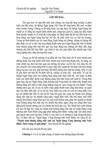
Requirements
•
Identify the new components that are required:
Example:
•
Above is an example of 6 Threeway pieces that are not be covered by the Standard
AVEVA Solutions Ltd sample HVAC catalogue.
4:2
PDMS 12.0
HVAC Administrator Guide
User Defined Components
•
4.1.3
To make these pieces available as User Defined HVAC Fittings, follow this tutorial
exercise:
Create Top Level Elements in the New Database
In the new catalogue database that has been created and added to the MDB, some top level
elements are created to store the user defined HVAC catalogue.
NEW CATA /My-udHVACcata setstar
DESCRIPTION 'My Catalogue for User Defined HVAC Fittings
NEW SECT *-DETTEXT
DESCRIPTION 'Detail text My Catalogue for User Defined HVAC Fittings'
NEW CATE *-DETCATE
DESCRIPTION 'Detail text My Catalogue for User Defined HVAC Fittings
NEW SPWL /My-udHVACspecs
PURP HVAC
NEW SPEC /My-udHVACspec
PURP FITT
QUESTION ELEM
TQUESTION 'Element Type
TDEFAULT 'NONE
Notice in the above that the SPWL purpose is set to HVAC and the SPEC purpose is set to
FITT. These settings are important because in DESIGN this specification will then be listed
on the HVAC User Defined Fittings form. Element type will be the first selector text on the
same form.
4.1.4
Identify an Existing Similar Component
The most efficient way for the Administrator to create a new component is to copy an
existing similar component and modify it.
Considering the 6 components in the example, copy /RSTHRE which is the standard
component definition for a Rectangular Square Threeway
4.1.5
Macros to Copy an Existing Component
Write some simple macros to copy the existing component.
Examples:
copyMac1
/My-udHVACcata
tail
new sect $1-SECT copy $2-SECT rename $2 $1
$.
4:3
PDMS 12.0
HVAC Administrator Guide
User Defined Components
copyMac2
$d2=
/My-udHVACcata-DETCATE
tail
new sdte $1 copy $2-DETAIL
rtext |$2|
$.
myUDCata
-- Macro to make My catalogue from copy of existing similar standard
$m/c:/MY-Macros/copyMac1
$m/c:/MY-Macros/copyMac2
$m/c:/MY-Macros/copyMac1
$m/c:/MY-Macros/copyMac2
$m/c:/MY-Macros/copyMac1
$m/c:/MY-Macros/copyMac2
/My-Y-Type-3-Way1 /RSTHRE
/My-Y-Type-3-Way1-Detail /RSTHRE
/My-Y-Type-3-Way2 /RSTHRE
/My-Y-Type-3-Way2-Detail /RSTHRE
/My-Y-Type-3-Way3 /RSTHRE
/My-Y-Type-3-Way3-Detail /RSTHRE
$m/c:/MY-Macros/copyMac1
$m/c:/MY-Macros/copyMac2
RSTHRE
$m/c:/MY-Macros/copyMac1
$m/c:/MY-Macros/copyMac2
RSTHRE
$m/c:/MY-Macros/copyMac1
$m/c:/MY-Macros/copyMac2
RSTHRE
/My-Angled-Type-3-Way1 /RSTHRE
/My-Angled-Type-3-Way1-Detail /
/My-Angled-Type-3-Way2 /RSTHRE
/My-Angled-Type-3-Way2-Detail /
/My-Angled-Type-3-Way3 /RSTHRE
/My-Angled-Type-3-Way3-Detail /
copyMac3
$1-GMSE
new DTSE $1-DTSE copy /RSTHRE -DETAIL-DATA rename /RSTHRE $1
NEX SCOM
DTREF $1-DTSE
myUDCataDtse
-- Macro to make My datasets from copy of existing similar standard
$m/c:/MY-Macros/copyMac3 /My-Y-Type-3-Way1 /RSTHRE
$m/c:/MY-Macros/copyMac3 /My-Y-Type-3-Way2 /RSTHRE
$m/c:/MY-Macros/copyMac3 /My-Y-Type-3-Way3 /RSTHRE
$m/c:/MY-Macros/copyMac3 /My-Angled-Type-3-Way1 /RSTHRE
$m/c:/MY-Macros/copyMac3 /My-Angled-Type-3-Way2 /RSTHRE
$m/c:/MY-Macros/copyMac3 /My-Angled-Type-3-Way3 /RSTHRE
4:4
PDMS 12.0
HVAC Administrator Guide
User Defined Components
4.1.6
Run the Catalogue Macros
In DESIGN or PARAGON (as discussed earlier)
$m//c:/MY-Macros/myUDCata
$m//c:/MY-Macros/myUDCataDtse
These macros will create the database elements for the 6 example components.
All elements will be named and organised in a consistent manner.
It is advised that all elements, including primitives and ppoint elements, are named.
The macros will output some catalogue errors but there is no need to be concerned about
these, this is simply because the model Design Parameters are not set at this stage.
Catalogue error for component SCOM /My-Y-Type-3-Way1, catalogue primitive PTMIX /MyY-Type-3-Way1-P6 - Design Parameter number ( 2 ) out of range.
4.1.7
Macros to Create Specification References
Write a simple macro to create a Specification reference for the catalogue components
created above.
myUDSpec
/ My-udHVACspec setst
tail
-- ---------------------------NEW SELEC */3ways setst
DESC 'Rectangular Threeways'
QUES SPEC
TANS 'THRE'
TDEF 'NONE'
TQUES 'Specific'
NEW SPCOMPONENT */Y-Type1
TANS 'Y Type1'
Catref /My-Y-Type-3-Way1
Detref /My-Y-Type-3-Way1-Detail
NEW SPCOMPONENT */Y-Type2
TANS 'Y Type2'
Catref /My-Y-Type-3-Way2
Detref /My-Y-Type-3-Way2-Detail
NEW SPCOMPONENT */Y-Type3
TANS 'Y Type3'
Catref /My-Y-Type-3-Way3
Detref /My-Y-Type-3-Way3-Detail
NEW SPCOMPONENT */Angled-Type1
4:5
PDMS 12.0
HVAC Administrator Guide
User Defined Components
TANS 'Angled Type1'
Catref /My-Angled-Type-3-Way1
Detref /My-Angled-Type-3-Way1-Detail
NEW SPCOMPONENT */Angled-Type2
TANS 'Angled Type2'
Catref /My-Angled-Type-3-Way2
Detref /My-Angled-Type-3-Way2-Detail
NEW SPCOMPONENT */Angled-Type3
TANS 'Angled Type3'
Catref /My-Angled-Type-3-Way3
Detref /My-Angled-Type-3-Way3-Detail
Reminder:
4.1.8
•
SPWL %purp HVAC, SPEC %purp FITT to appear in the HVAC User Defined Fittings
form.
•
Each level of SELE with %tquestion and %tans causes a further level of questions in
the HVAC UD Fittings form.
•
Beware that a too lengthy %tans may prevent it from fitting into the form.
Run the Specification Macro
In DESIGN or PARAGON (as discussed earlier)
$m//c:/MY-Macros/myUDSpec
These macros will create the specification elements for the 6 example components. The
TANS texts are the words that will appear on the Design form for User defined HVAC fittings.
4.1.9
Observe the User Defined HVAC Fittings form
In Design-HVAC Designer Application and from the HVAC form select Category 'User
Defined Fittings'.
4:6
PDMS 12.0
HVAC Administrator Guide
User Defined Components
The Specification created is displayed, and the selectors available to select the 6 catalogue
items. At the moment if you select any of these they will all be the same as the copied
component /RSTHRE. So the next stage is to edit these components to be unique to match
the initial requirements.
4.1.10
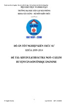
Make a Sketch
For the example choose to make the 1st component of the 6 Threeway components
illustrated previously. Make a pencil sketch of the component and mark it with all the
variable Design Parameters to be used. It is recommended that the Administrator follows,
as closely as possible to the list of Design Parameter/Properties listed in the HVAC User
Guide appendix B. For example DESP[2] and DESP[3] are the arrive duct size etc.
4:7
PDMS 12.0
HVAC Administrator Guide
User Defined Components
4.1.11
4.1.12
Some Conventions
•
The component origin P0 is generally at the intersection of P1 and P2.
•
P1 is normally the arrive point, P2 is the leave point and P3 is any third connection
point.
•
For straight components P0 is normally at the arrive point, however for the likes of
dampers, valves or grilles P0 will be wherever sensible, may be central or even at P2.
•
The axes are shown on the sketch above as used on HVAC components where Z is
opposite to the PArrive, X and Y are the respective width and height of the arrive duct
size.
•
On angled components PLeave is primarily towards X rather than -X.
Edit the Detail Text
The detail text is in the DATASET created earlier (i.e. /My-Y-Type-3-Way1-DTSE).
This is presently a direct copy of the copied Threeway so it needs to be modified
accordingly, such as: Rtext 'Rectangular Special Threeway Y type1'
4.1.13
Edit the Properties
Because the example was copied from a standard component then the full list of properties
has been inherited. A full list is available in the HVAC Designer User Guide.
It is therefore necessary to decide which properties are required for input for the new
component.
The properties are in the DATASET created earlier (i.e. /My-Y-Type-3-Way1-DTSE).
4:8
PDMS 12.0
- Xem thêm -