VIETNAM NATIONAL UNIVESITY HANOI
VIETNAM JAPAN UNIVERSITY
HOANG DUY PHUONG
ANALYTICAL AND NUMERICAL
ANALYSES ON STIFFNESS
ENHANCEMENT OF GROUND
IMPROVED BY HEAD-ENLARGED CDM
COLUMNS
MAJOR: INFRASTRUCTURE ENGINEERING
CODE: 8900201.04QTD
RESEARCH SUPERVISOR
Dr. NGUYEN TIEN DUNG
MASTER’S THESIS
Hanoi, 2020
TABLE OF CONTENTS
ABSTRACT ......................................................................................................................
ACKNOWLEDGEMENTS ..............................................................................................
LIST OF TABLES ............................................................................................................
LIST OF FIGURES ...........................................................................................................
LIST OF ABBREVIATIONS ...........................................................................................
CHAPTER I: INTRODUCTION .................................................................................... 1
1.1. General introduction of deep mixing method........................................................... 1
1.2 Necessity of research ................................................................................................. 2
1.3 Objective and Scope of research ........................................................................... 3
1.3.1 Objective of the study .......................................................................................... 3
1.3.2 Scope of the study ................................................................................................ 3
CHAPTER 2: LITERATURE REVIEW......................................................................... 4
2.1 Overview of deep mixing method ............................................................................. 4
2.1.1 Brief view of deep mixing method ....................................................................... 4
2.1.2 Application of CDM ............................................................................................ 6
2.1.3 Classification....................................................................................................... 8
2.1.4 Equipment and machine .................................................................................... 10
2.1.5 Construction procedure .................................................................................... 11
2.1.6 Fixed type and floating type improvement ........................................................ 12
2.2 Improvement of conventional CDM method .......................................................... 12
2.2.1 T-shaped soil- cement column ........................................................................... 12
2.2.2 The PF method .................................................................................................. 15
2.3 Theory of settlement evaluation .............................................................................. 16
2.3.1 The equivalent elastic modulus and 3D settlement of composite grounds ....... 16
2.4 Theory of numerical method ................................................................................... 18
2.4.1 Preliminaries on material modelling ................................................................ 18
2.4.2 Linear elastic model .......................................................................................... 18
2.4.3 Mohr-Coulomb model ....................................................................................... 21
2.4.4 Hardening soil model ........................................................................................ 24
2.4.5 Soft soil model ................................................................................................... 33
CHAPTER 3: METHODOLOGY ................................................................................. 35
3.1 Analysis approaches ................................................................................................ 35
3.2 Analyses using analytical method ........................................................................... 36
3.3 Analyses using numerical method ........................................................................... 38
CHAPTER 4: LABORATORY AND FIELD TEST .................................................... 40
4.1 Introduction of Samse project ................................................................................. 40
4.1.1 General information of project ...................................................................... 40
4.1.2 The PF groups ................................................................................................ 40
4.1.3 Soil profile and footing parameters ............................................................... 41
4.2 Laboratory tests for Samse project .......................................................................... 43
4.3 Static load test on PF groups ................................................................................... 47
4.3.1 The geometry and installation PF groups ...................................................... 47
4.3.2 Installing strain gauges .................................................................................. 48
4.4 Static load test on single PF column........................................................................ 49
4.4.1 Soil profile ..................................................................................................... 49
4.4.2 Footing parameters ........................................................................................ 49
CHAPTER 5: SETTLEMENT ANALYSIS AND RESULTS ..................................... 51
5.1 Settlement analyses using elastic theories ............................................................... 51
5.1.1 Verification analysis.......................................................................................... 51
5.1.2 Analyses for Ideal case and JEF case ............................................................... 52
5.1.3 Results and discussions ..................................................................................... 56
5.2 Settlement analyses using nonlinear models ........................................................... 61
5.2.1 Analyses for ideal case ...................................................................................... 61
5.2.2 Analyses for the experimental single PF column.............................................. 62
5.2.3 Analyses for PF groups at SAMSE project ....................................................... 63
CHAPTER 6: CONCLUSIONS AND RECOMMENDATIONS ................................ 71
6.1 Conclusions .......................................................................................................... 71
6.2 Limitations and suggestions ................................................................................. 72
REFERENCES .............................................................................................................. 73
APPENDIX ................................................................................................................... 76
ABSTRACT
Point Foundation (PF) method is an advanced technology introduced by EXT Co. Ltd
company from Korea, which has more advantages than CDM method. The shape of PF
columns makes a big difference in settlement compared to conventional CDM.
This study presents a comparative study on stiffness enhancement of grounds improved by
Point Foundation method and by the conventional CDM method using analytical and
numerical analyses. In addition, the analysis results are compared with experimental
program.
The stiffness enhancement is evaluated through induced settlement values under four
shallow footing cases, of which one is ideally assumed and the other is an actual footing
constructed. Results from both analytical analysis and numerical analysis, in which elastic
models are used, indicate that in general the PF method produces a more proper stiffness
distribution with depth, which in turn results in smaller settlement values. Numerical
analysis results also indicate that when only soil area under the footing is improved
settlement of the footing is significantly larger than that on ground improved entirely, the
case of theoretical elastic soil model. This is attributed to the influence of larger horizontal
displacement around the footing.
Results from numerical analysis, in which inelastic model used, settlement of shallow
footing on PF columns is smaller settlement of conventional CDM columns for the same
ground model under certain conditions.
By true 3D model of column and soil, when the load-settlement is still in relatively linear
range, the settlement values from the equivalent soil model and true 3D column and soil
model are relatively equal. This may suggest the equivalent soil model can be used in
practice as it has been used in the elastic analyses. PF columns has been analyzed the true
behavior between columns and soil (shape of PF column, interaction between column and
soil), the results analysis show that when analyzing settlement of shallow footings on PF
columns in soft clay, special attention should be paid to the stiffness ratio between PF
column and soil.
ACKNOWLEDGEMENTS
I would like to express my sincere appreciation for the lecturers of Master of Infrastructure
Engineering Program for their help during my undergraduate at Vietnam Japan University
(VJU).
First of all, I am very grateful Dr. Nguyen Tien Dung, who guided me to conduct this thesis
for the part one year. He spent a lot of time telling me complicated issues in geotechnical
engineering. Not about knowledge, he also taught me valuable lesson about the seriousness
and carefulness in scientific research. These valuable lessons will follow me throughout
the future study.
I would like to acknowledge the sincere inspiration from Prof. Nguyen Dinh Duc
and Prof. Hironori Kato. Their lectures covered not only specialist knowledge but
also the responsibility and mission of a new generation of Vietnam. I am grateful to Dr.
Phan Le Binh for his support in the last two years since I have studied at Vietnam Japan
University. Thanks to him, I have learned the professional courtesy of Japanese people as
well as Japanese culture. I would also like to acknowledge the staff of Vietnam Japan
University, Mr. Bui Hoang Tan for their help and support. I would also like to thank Prof.
Junichi Koseki, Assoc. Prof. Kenji Watanabe, Assist Prof. Hiroyuki Kyokawa as well as
other members of Koseki lab, where I had 80 meaningful days internship at The University
of Tokyo. It was very helpful to me.
Special thanks to Associate professor Nguyen Chau Lan, lecturer at University of
Transport and Communication. His explanations in geotechnical engineering helped me a
lot in this study. His successful way in research encouraged me more than anything else.
Thanks to Dr. Nguyen Cong Oanh (Vietnam Academic for Water Resources), he explained
in detail the complex problems in finite element method for geotechnical engineering.
Finally, Thanks are due to my family, who are always and support me in studies and
research.
LIST OF TABLES
Table 2.1 Typical properties of Stabilized soil (wet method) (Modified from Elias et al.
2006) ................................................................................................................................... 5
Table 2.2 Typical Properties of Lime–Cement Stabilized Soils (Dry Method) (Modified
from Elias et al. 2006)......................................................................................................... 5
Table 4.1 Unconfined compression test results ................................................................ 44
Table 4.2 Strength parameters of samples collected from the PF column. ...................... 50
Table 5.1 Input parameters for calibration analysis .......................................................... 52
Table 5.2 Input parameters for settlement analysis ......................................................... 55
Table 5.3 Input parameters for the single PF column ....................................................... 63
Table 5.4 Material model and parameter used for Samse factory project. ....................... 64
LIST OF FIGURES
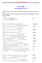
Figure 1.1 Configuration of improved CDM columns: (a) Point foundation (PF) (Nguyen
et al. 2019a): (b) T-shape column (Liu et al. 2012) ............................................................ 2
Figure 2.1 Available ground improvement methods for different soil types (modified from
Schaefer et al., 2012) .......................................................................................................... 8
Figure 2.2 Classification of deep mixing method (Kitazume & Terashi, 2013) ................ 9
Figure 2.3 Equipment of deep mixing method (DJM machine) ....................................... 10
Figure 2.4 Drilling machine (left) and Mixing shaft and blades of DJM machine (right) 11
Figure 2.5 Machine has two mixing shafts and Binder Plant for DJM method (by the
courtesy of Dry Jet Mixing Association) .......................................................................... 11
Figure 2.6 Type of ground improvement (Kitazume & Terashi, 2013) ........................... 12
Figure 2.7 The T-shaped soil cement column overlain by embankment (Song-Yu at el,
2012) ................................................................................................................................. 14
Figure 2.8 Displacement of soil under TDM and SCC (Yaolin et al., 2012) ................... 14
Figure 2.9 Load- settlement curves of conventional DCM and TDM pile from physical
model test (Chana Phutthananon et al, 2012) ................................................................... 15
Figure 2.10 Site construction of PF method ..................................................................... 16
Figure 2.11 Flexible rectangular loaded area.................................................................... 16
Figure 2.12 General three demensional coordinate systems and sign convention for stress
........................................................................................................................................... 19
Figure 2.13 Basic ideal of an elastic perfectly plastic model (Plaxis manual) ................. 22
Figure 2.14 The Mohr-Coulomb yield surface in the principal stress space (c=0) .......... 23
Figure 2.15 Hyperbolic stress- strain curve (Ducan & Chang, 1970) .............................. 25
Figure 2.16 Stress circles at yield (Plaxis manual) ........................................................... 26
Figure 2.17 Relationship between initial tangent modulus and confining pressure ......... 27
Figure 2.18 Unloading and reloading of silica sand under drain triaxial test consolidation
(Ducan and Chang 1970) .................................................................................................. 28
Figure 2.19 Hyperbolic stress–strain relationship in primary loading for a standard drained
triaxial test (Schanz, 1999) ............................................................................................... 30
Figure 2.20 Representation total yield of the HS model in principle space stress for
cohesionless soil................................................................................................................ 31
Figure 2.21 Yield surface of hardening model (Schanz et al., 1999) ............................... 32
Figure 3. 1 Configuration of CDM and PF columns ........................................................ 35
Figure 4. 1 Plan view of SAMSE factory project ............................................................. 40
Figure 4. 2 Plan view of three PF groups ......................................................................... 41
Figure 4.3 Shape of PF columns: (Left) Group 1 (LPF=8.5m), (Middle) Group 2 (LPF=6 m);
........................................................................................................................................... 42
Figure 4.4 Soil profile of SAMSE factory project ............................................................ 42
Figure 4.5 Collection of mixed cement- soil samples ...................................................... 45
Figure 4.6 Secant Modulus E50 ......................................................................................... 46
Figure 4.7 Relationship between secant modulus of elasticity and unconfined compressive
strength (SAMSE project) ................................................................................................ 46
Figure 4.8 Static load test on instrumented PF groups ..................................................... 47
Figure 4.9 Test installation: (a) the geometry of PF columns, (b) increment load applies on
steel plate, (c) displacement sensors on steel plate and groundb...................................... 47
Figure 4.10 Strain gauge installation: (a) installation of sensors along the depth of PF, (b)
setting up sensors into PF, (c) strain gauge instruments, (d) sensor in PF ....................... 48
Figure 4.11 Soil profile at Songdo site (Kim et al. 2016). ................................................ 49
Figure 4.12 Configuration of the instrumented column (Kim et al. 2016) ....................... 50
Figure 4.13 Instrumentations implemented on variable cross-section soft ground reinforced
foundation (Kim et al. 2016)............................................................................................. 50
Figure 5.1 Foundation and soil domain in the numerical analysis ................................... 51
Figure 5.2 Comparison of vertical stress profiles obtained from analytical and numerical
analyses ............................................................................................................................. 52
Figure 5.3 Soil profile under the examined footings (Ideal case)..................................... 53
Figure 5.4 Soil profile under the examined footings (JEF project) .................................. 54
Figure 5.5 Cross-sectional and plan views of the examined footing at JFE project......... 55
Figure 5.6 Settlement value from analytical method for Ideal case ................................. 57
Figure 5.7 Settlement value from analytical method for JEF case ................................... 58
Figure 5.8 Variation of Scorr,PF,min/Scorr,CMD ratio................................................................ 58
Figure 5.9 Settlement values from analytical and numerical analyses for Ideal case ...... 59
Figure 5.10 Settlement values from analytical and numerical analyses for JEF project .. 60
Figure 5.11 Settlement analysis from numerical method for ideal case .......................... 61
Figure 5.12 Settlement analysis from numerical method for JEF case ............................ 61
Figure 5.13 Load- settlement curves from MC model ..................................................... 62
Figure 5.14 Load settlement curves from Numerical method for PF column and
conventional CDM ............................................................................................................ 63
Figure 5.15 Load settlement curves from Numerical method for PF columns and CDM
columns using equivalent material (E50=150qu) ............................................................... 65
Figure 5.16 Load settlement curves from Numerical method for PF groups and CDM
groups using true 3D model of PF columns and soil ........................................................ 66
Figure 5.17 Settlement profiles with depth of footings on PF and CDM columns from
numerical method using equivalent material model (q = 800 kPa) .................................. 68
Figure 5.18 Load settlement curves from Numerical method for PF columns and
conventional CDM columns (Optimal shape design for PF columns) ............................. 68
Figure 5.19 Variation of settlement () and effective vertical stress (v) at the toe of CDM
and PF columns obtained from numerical analysis using true 3D model ........................ 69
Figure 5.20 Mohr- Coulomb failure criterion ................................................................... 76
LIST OF ABBREVIATIONS
as
ascc
CDM
c (c’)
Cc
Cs
D
Dh
Df
Dt
eo
Ei
Eoed
E50
Eu
Eur
Ec
Ecomp
Es
E’s
HCC
HS
L
Lc
Lh
Lt
M
MC
Ms
NC
OCR
PF
PI
qu
Improvement area ratio
Improvement area ratio of conventional CDM column
Cement deep mixing method
Cohesion strength
Compression index
Swelling index
Diameter of conventional soil cement column (m)
Diameter of cap of HCC (m)
Embedded depth (m)
Diameter of tail of HCC (m)
Initial void ratio
Initial tangent modulus
Oedometric modulus
Scant elastic modulus of soil at 50 percent (kPa)
Undrained elastic modulus of soil (kPa)
Unloading and reloading Young’s modulus
Elastic modulus of soil cement column (kPa)
Elastic modulus of improved ground (kPa)
Elastic modulus of soil (kPa)
Young’s modulus in term of effective stress
Head-enlarged soil cement column
Hardening soil model
Length of conventional soil cement column (m)
Length of cone of PF column (m)
Length of head of PF column (m)
Length of tail of PF column (m)
Shape factor for Cam clay ellipse/slope of critical state
line
Mohr Coulomb model
Constrained modulus of soil (kPa)
Normal consolidation
Over consolidation ratio
Point foundation
Plasticity index (%)
Unconfined compressive strength (kPa)
q
p’
CDM
SS model
Su
TDM
xy
z
u
ur
Deviator stress
Mean effective stress
Conventional soil cement column
Soft soil model
Undrained shear strength of soil (kPa)
T-shaped deep mixed column
Ratio of length of cap and the total length of PF column
Ratio of diameter of cap of HCC and diameter of tail of
PF column
Horizontal stress increment (kPa)
Vertical stress increment (kPa)
Ratio of distance between two columns and the diameter
of column
Poisson ratio of soil in drained condition
Poisson ratio of soil in undrained condition
Poisson ratio for unloading and reloading
CHAPTER I: INTRODUCTION
1.1.
General introduction of deep mixing method
The sustainability of the building depends largely on the foundation of the building
(about from 40 to 60% value of project). Therefore, the design of the foundation is an
important element in the design work. Under the development of science and
technology, there are many foundation design options that are widely used.
Nowadays, there are many methods for improving soft grounds such as compaction
methods, vertical drains under surcharge and vacuum preloading, vibration methods,
deep mixing method, and other miscellaneous methods. Among the methods, deep
mixing method (DMM) is widely used as an effective method for ground reinforcement
in the world. The method creates cement deep mixing (CDM) columns to increase the
stiffness (i.e., to reduce settlement) and to control the stability of embankment or
excavations. In general, sub-soils at different places have unique behavior under same
loading condition so that finding an optimal solution that satisfies both technical and
financial requirements is always an interesting question for geotechnical engineers.
The DMM has been extensively used for many types of construction project, for
example embankment supports, buildings, earth retaining structures, retrofit and
renovation of urban infrastructures, liquefaction hazards mitigation, manmade island
construction and seepage control. Deep mixing has been mostly used to improve soft
cohesive soils, but it is sometimes used to reduce permeability and mitigate liquefaction
of cohesionless soils.
Besides the advantages, the conventional CDM column also has some limitations when
it is applied to reinforce grounds under shallow foundations. Soil layers in the upper part
is often weaker than that in the lower part (deeper layers), however, under shallow
footings, introduced stresses are mainly distributed in the depths right below the footing.
This combination of natural ground and CDM columns in cases of shallow footings is
therefore ineffective. There should be a better shape of CDM columns to reinforce the
ground more optimal.
1
1.2 Necessity of research
Recognizing the limitations of CDM columns as stated above, EXT Co. Ltd company
from Korea have recently introduced an improved type of CDM column and named it
“point foundation” (PF). In principle, the PF column has three distinct parts (Fig. 1.1a):
The bigger head (upper part), the transitional cone and the smaller tail. The configuration
of the PF column and its construction method were introduced in Trung (2019), Nguyen
et al. (2019a and 2019 b).
Liu et al. (2012) developed special equipment that has foldable augers to install deep
mixing (DM) columns at different diameters. Due to the shape of the columns like the
letter T, they are named this DM columns T-shaped columns (Fig. 1.1b). Some
researches on T-shaped soil cement column (e.g., Yi et al. 2018) showed remarkable
results in settlement and lateral movement reduction compared with conventional
method.
P
Linear layer
Dh
Dt
Soil layer i
Gravel (bed rock)
Depth (m)
hi
Stress increment ( p)
profile
Soft soil
layer
Lt
L
Lc
Lh
Df
tf
tl
Fill
(a)
(b)
Figure 1.1 Configuration of improved CDM columns: (a) Point foundation (PF)
(Nguyen et al. 2019a): (b) T-shape column (Liu et al. 2012)
Although there were some initial researches on PF columns (i.e., Trung 2019, Nguyen
et al. 2019), these studies focused on introduction of concept of the method as well as
of a simple analytical method to evaluate settlement of soft ground improved by the PF
columns.
Much of understandings on the PF columns under shallow foundations, such as the
influence or nonlinearity of soil and the influence of stiffness of PF columns to the
settlement of the foundations are unfolded. It is therefore necessary to have a study to
2
further understand the behavior of PF groups under actual foundation conditions (e.g.,
actual soil layers, nonlinear characteristics of soil materials).
1.3 Objective and Scope of research
1.3.1 Objective of the study
General objective:
To evaluate the effectiveness of PF columns over that of CDM columns in reducing
settlement of shallow footings on reinforced grounds using both analytical and
numerical methods for the same foundation models.
Specific objectives:
1. To evaluate the effectiveness when the soil layers are modelled as elastic materials
using both analytical and numerical methods.
2. To evaluate the effectiveness when the soil layers are modelled as inelastic materials
using numerical method.
3. To evaluate the effectiveness when the treated zone under the footing is modelled as:
(i) an equivalent material; (ii) a true 3D model of PF columns and soil.
1.3.2 Scope of the study
To obtain the objectives above, this study focuses on the following:
1. Evaluate settlement of shallow footings using classical theory of foundation on
elastic materials. For this, settlement of shallow footings on an ideal soil profile and
on an actual project soil profile is evaluated using both analytical and numerical
methods.
2. Compare predicted and measured settlement values of shallow footings using nonlinear behavior of soil material. For this, settlement of shallow footings on an
experimental single PF column and on experimental PF groups is evaluated using
numerical method.
3. Compare predicted and measured settlement values of shallow footings on
experimental PF groups, in which the treated zone is modelled as an equivalent
elastic material and as a true 3D model of PF columns and soil.
3
CHAPTER 2: LITERATURE REVIEW
2.1 Overview of deep mixing method
As mentioned in the objective section of this report, this study focuses on reducing the
settlement of soft ground. Hence, a critical overview of soil cement column, as well as the
behavior of composite ground, will be considered first then the theory of settlement
evaluation will be assessed for choosing the appropriate methods for the calculation of this
study. In the lieterature, there are many researches on deep mixing method (or cement deep
mixed soil column), of which some typical studies are Kitazume and Terashi (2013),
Bergado (1996), Rujikiatkamjorn et al. (2005), Chai and Carter (2011), Han (2015), Bruce
et al. (2013), Bredenberg et al. (1999), Kirsch and Bell (2012).
2.1.1 Brief view of deep mixing method
As mentioned in the introduction, deep mixing method increases the stiffness of ground by
mixing in-situ soil with admixture (cement and necessary additives). Mixed soil columns
created by deep mixing method has the elastic modulus at 50 percent (E50) of 75 to 1,000
times qu, where qu is the unconfined compressive strength of the column material
(Kitazume & Terashi, 2013), but the value is still smaller than that of concrete pile
(30,000,000 kPa). Thus, It can be considered that the work of mixed soil columns and
surrounding soft soil as composited ground (not pile). Base on this assumption, most
previous scholars proposed an equivalent elastic modulus of composited ground for
determining the stiffness as well as deformation.
The typical properties of stabilized soils are provided in Table 1.1 based on the wet method
of deep mixing and Table 1.2 based on the dry method of deep mixing. The effects of
different factors on the unconfined compressive strengths of stabilized soils have been
discussed above.
4
Table 2.1 Typical properties of Stabilized soil (wet method) (Modified from Elias et al.
2006)
Table 2.2 Typical Properties of Lime–Cement Stabilized Soils (Dry Method) (Modified
from Elias et al. 2006)
5
2.1.2 Application of CDM
Selection of ground improvement method should consider the following conditions: (1)
structural conditions, (2) geotechnical conditions, (3) environmental constraints, (4)
construction conditions, and (5) reliability and durability.
Structural conditions: The structural conditions may include type, shape, and dimension
of structure and footing, flexibility and ductility of structural and footing elements, type,
magnitude, and distribution of loads, and performance requirements (e.g., total and
differential
settlements,
lateral
movement,
and
factor
of
safety).
Geotechnical conditions: The geotechnical conditions may include geographic landscape,
geologic formations, type, location, and thickness of problematic geo-material possible
end-bearing stratum, age, composition, distribution of fill, and groundwater table. Soil type
and particle size distribution are essential for preliminary selection of ground improvement
methods as shown in Figure 2.1. This guideline is suitable for ground improvement
methods for foundation support. The thickness and location of problematic geo-material
are also important for the selection of ground improvement methods. For example, when a
thin problematic geo-material layer exists at a shallow depth, the over excavation and
replacement method is one of the most suitable and economic method. When a relatively
thick loose cohesionless geo-material layer exists near ground surface, dynamic
compaction and vibro-compaction methods are suitable ground improvement methods.
When a relatively thick soft cohesive geo-material layer exists near ground surface,
preloading and deep mixing methods may be used. When a site needs to be excavated,
tieback anchors, soil nails, deep mixed columns, and jet grouted columns may be used.
When a site needs to be elevated, geo-synthetic-reinforced slopes and walls can be good
choices. The level of groundwater table often affects the selection of ground improvement
methods. For example, when deep excavation happens in ground with a high groundwater
table, deep mixed column walls may be better than soil nailed walls because they not only
can retain the geo-material but also can cut off water flow.
Environmental constraint: The environmental constraints may include limited vibration,
noise, traffic, water pollution, deformation to existing structures, spoil, and headspace. For
example, dynamic compaction induces vibration and noise, which may not be suitable in a
6
residential area. The wet method to construct stone columns by water jetting produces spoil
on site, which may be troublesome for a site with limited space. Under such a condition,
the dry method may be used instead. Preloading induces settlements at nearby areas, which
may be detrimental to existing structures.
The selection of a ground improvement method should consider the following construction
conditions: (1) site condition, (2) allowed construction time, (3) availability of construction
material, (4) availability of construction equipment and qualified contractor, and (5)
construction cost. The selection of a ground improvement method must consider whether
the site is accessible to its associated construction equipment, such as access road and
headspace. Construction time is one of the most important factors for the selection of a
ground improvement method. For example, preloading is a cost-effective ground
improvement method to improve soft soil; however, it takes time for the soil to consolidate.
The use of prefabricated vertical drains can accelerate the rate of consolidation, but
sometimes it still may not meet time requirement. As a result, other accelerated ground
improvement methods may be used, such as deep mixing and vibro concrete column
methods. Most ground improvement methods use specific materials during construction.
For example, stone columns and rammed aggregate columns use aggregate. Cement is used
for deep mixing and grouting. When natural material is used, such as aggregate or sand,
the cost of the material depends on the source of the material and its associated
transportation distance. For example, in a mountain area, aggregate is often less expensive;
therefore, stone columns or aggregate columns are often a cost-effective solution. In
general, the use of locally available material results in more cost-effective ground
improvement. To select a ground improvement method, engineers should gather
information about possible qualified contractors and their available construction
equipment. It is preferable to use a locally available qualified contractor because this will
reduce the mobilization cost and the contractor is more familiar with local conditions.
Construction cost is always one of the key factors that dominate the selection of a ground
improvement method. The construction cost should include mobilization, installation,
material, and possible disposal costs.
7
Reliability and Durability Reliability of a ground improvement method depends on several
factors, such as the level of establishment, variability of geotechnical and structural
conditions, variability of construction material, quality of the contractor, quality of
installation, and quality control and assurance. Several researchers have exported that
samples from deep mixed columns have a high variability in terms of their unconfined
compressive strengths. Automatic or computer-controlled installation processes can reduce
the variability of improved geo-materials. The number of well documented successful or
failure case histories is also the evidence of the reliability of a specific ground improvement
method. Ground improvement methods are used for temporary and permanent structures.
For permanent structures, the durability of the construction material should be evaluated
or considered in the design. For example, geosynthetics have creep behavior. The corrosion
of steel reinforcement with time reduces its thickness. The strength of cement-stabilized
soil in seawater degrades with time (Ikegami et al., 2002).
Figure 2.1 Available ground improvement methods for different soil types (modified
from Schaefer et al., 2012)
2.1.3 Classification
The techniques most commonly employed for in-situ deep mixing in Japan can be divided
into three groups: mechanical mixing by vertical rotary shafts with mixing blades at the
8
bottom end of each mixing shaft, high pressure injection mixing, and combination of the
mechanical mixing and high pressure injection mixing. The various methods in these
groups are classified in Figure 5.1. In the mechanical mixing techniques, binder is injected
into a ground with relatively low pressure and forcibly mixed with the soil by mixing blades
equipped to vertical mixing shaft(s). The binder is used either with powder form (dry
method) or slurry form (wet method). The Dry Jet Mixing (DJM) method is the most
common dry method of deep mixing and has usually been applied for on-land works (Dry
Jet Mixing Association, 2010).
Figure 2.2 Classification of deep mixing method (Kitazume & Terashi, 2013)
The Cement Deep Mixing (CDM) method, the most common wet method of deep
mixing, has frequently been applied for both in-water and on-land works (Cement
Deep Mixing Method Association, 1999). In the high pressure injection technique, on the
other hand, ground is disturbed by a high pressure jet of water and/or air, while at the same
9
- Xem thêm -